

No component in a 24/7 industrial process is ever truly passive. Every bearing, seal, motor, and coupling in a continuous operation system is under constant load, cycling through thermal expansion and contraction, and accumulating wear that, if undetected, will eventually force an unplanned stop. Of all the rotating components in a typical continuous process plant — petrochemical refinery, pulp mill, port conveyor, water treatment facility — the coupling is among the most frequently misunderstood and consequently the most unnecessarily expensive to maintain.
The challenge is not that couplings are inherently unreliable. It is that the maintenance culture in many industrial facilities treats coupling service life as something that happens to them rather than something they engineer. This article shifts that perspective, providing the framework for proactive management of coupling performance in continuous operation environments.
1. The Physics of Coupling Under Continuous Load
A coupling in continuous service operates under a fundamentally different load regime than one in intermittent or standby service. The continuous system experiences sustained torque at near-rated load for extended periods, thermal cycling from ambient temperature changes and load fluctuations, vibration from equipment interactions, and constant exposure to process contamination — dust, moisture, chemical vapors, or airborne particulates that can degrade flexible elements.
The most demanding condition in continuous service is not peak torque but sustained sub-peak torque combined with high-speed operation. Under these conditions, fatigue accumulation in flexible elements — grids, elastomers, discs — follows a cumulative damage model. A coupling operating at 85% of rated torque continuously, with 2-hour daily starts and stops, accumulates more fatigue damage in 12 months than one operating at 60% rated torque with identical start-stop frequency. Understanding this load profile is essential for correct specification.
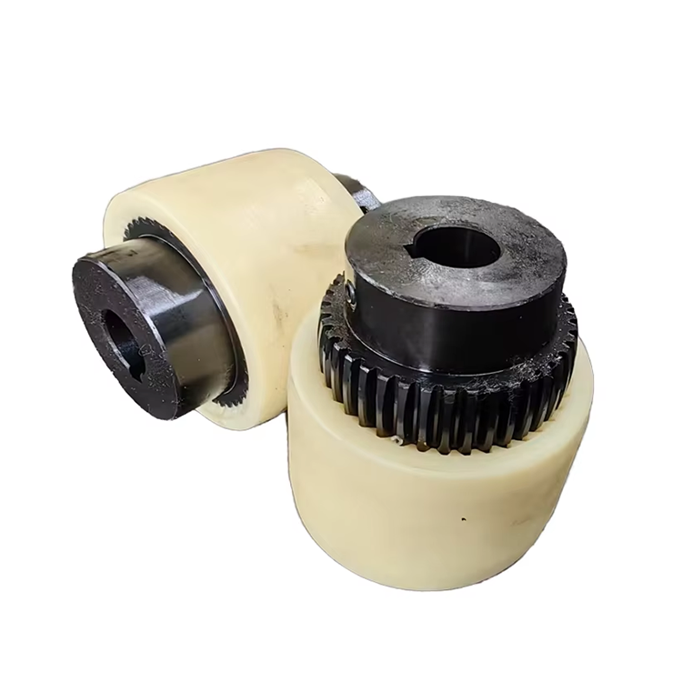
2. Matching Coupling Type to the Continuous Operation Profile
Not all coupling types are suited to continuous operation. The selection must account for the primary driven equipment type, the typical load profile, the environmental conditions, and the consequence of failure.
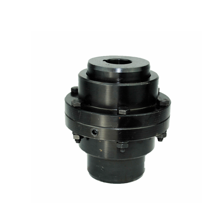
Gear couplings remain the workhorse for continuous high-torque applications such as large pump drives, compressors, and Long Distance Conveyors in mining. Their all-metal construction provides excellent high-temperature capability and long service life under continuous load. The requirement for regular lubrication — typically every 2,000–4,000 operating hours — is manageable in continuous systems when incorporated into planned maintenance schedules.
Industrial Grid Coupling designs are particularly well-suited to continuous conveyor systems where misalignment accommodation, shock load resistance, and low maintenance requirements are simultaneously important. The grid element provides the flexibility needed to handle thermal shaft growth and foundation settlement without imposing excessive bearing loads — a key advantage in Long Distance Conveyors where multiple drive stations and idler sections create complex alignment geometries.
Disc couplings offer an attractive maintenance-free alternative for continuous pump and compressor applications where alignment is well-controlled and torque peaks are within specification. Without wearing flexible elements, disc couplings can run for years without intervention — but they provide no misalignment tolerance beyond the initial alignment precision, making them unsuitable for applications with high dynamic misalignment.
3. Alignment as a Continuous Operation Discipline
Alignment is not a one-time installation task — it is a continuous discipline in 24/7 operation. Thermal growth alone shifts shaft positions by 0.1–0.5 mm in most industrial drive systems between cold startup and full operating temperature. Foundation settlement, equipment vibration, pipe stress, and coupling wear all alter alignment over time.
The most effective continuous operation facilities treat alignment verification as part of their regular equipment inspection routine. Laser alignment checks every 6–12 months for critical coupling connections in continuous service, combined with annual thermal growth mapping for equipment with significant temperature gradients, provide the data needed to schedule correction before misalignment exceeds tolerance limits.
For Long Distance Conveyors with multiple drive stations, alignment management extends beyond individual coupling connections to the overall conveyor structure. Belt tension, conveyor frame alignment, and pulley position all interact to affect the alignment condition at each drive shaft. A holistic approach to alignment management — treating the conveyor as a system, not a collection of individual components — consistently outperforms component-by-component alignment efforts.
4. Lubrication Strategy for Continuous Operation Couplings
Lubrication of gear and Industrial Grid Coupling components in continuous service follows different principles from general-purpose applications. The lubricant serves multiple functions simultaneously: reducing friction between moving elements, preventing corrosion of steel surfaces, dissipating heat from frictional losses, and protecting against particulate contamination.
For Industrial Grid Coupling installations, high-quality lithium-complex grease with EP (extreme pressure) additives is the standard recommendation. Grease interval depends on operating environment: in dusty mining environments, more frequent greasing (every 1,000–2,000 hours) may be necessary to prevent abrasive contamination of the grid slots, while in clean plant environments, intervals of 3,000–5,000 operating hours are typically sufficient.
Automatic lubrication systems — grease pumps with programmable delivery timers — are increasingly adopted in continuous operation facilities for Long Distance Conveyors and similar high-uptime-critical equipment. These systems maintain consistent lubricant film even during periods when maintenance access is restricted, reducing the risk of lubricant starvation and accelerated wear.
5. Vibration Analysis as a Predictive Coupling Monitoring Tool
Vibration analysis is one of the most powerful non-invasive tools for monitoring coupling condition in continuous operation systems. A degraded coupling element produces characteristic vibration signatures that are distinguishable from bearing faults, unbalance, or misalignment in adjacent components — when the analyst knows what to look for.
The key vibration signatures for coupling condition monitoring include:
Harmonic patterns at multiples of shaft speed in angular misalignment conditions, elevated radial vibration at coupling natural frequencies during parallel misalignment, and broadband energy increase in the 500 Hz–2 kHz range when flexible elements begin to lose stiffness through fatigue or contamination. Facilities with established vibration monitoring programs typically achieve 4–8 weeks of advance warning of coupling element degradation — sufficient time to plan a scheduled replacement during a planned outage rather than an emergency shutdown.
6. Spare Parts Strategy for Critical Continuous Operations
The consequence of coupling failure in a critical continuous operation — a liquefied natural gas plant, a port shiploader, or a 10,000 tpd mining conveyor — justifies investment in strategic spare parts inventory. The critical elements to stock are the flexible element (grid, disc, jaw insert) and the most commonly replaced wearing components such as seals, gaskets, and fasteners.
When sourcing spares, sourcing from the original T20 Grid Coupling Supplier or an authorized distributor ensures material properties match the original design specification. After-market grid elements from unknown suppliers have exhibited hardness variations of ±15% from nominal in metallurgical testing — significant enough to change fatigue life by 30–50% under equivalent loading conditions. The marginal cost premium of OEM spares is a fraction of the risk premium from using non-conforming alternatives.
7. Failure Mode Analysis and Root Cause Investigation
When a coupling does fail in continuous operation, the failure mode contains critical information for preventing recurrence. A systematic failure analysis protocol should be part of every maintenance engineer's toolkit.
Grid fractures in Industrial Grid Coupling applications reveal their cause in the fracture surface morphology: fatigue cracks originate at stress concentration points (typically the root of the grid slot or the transition radius at the grid end) and propagate with characteristic striation patterns under cyclic loading. Overload fractures, by contrast, show fibrous or shear fracture surfaces with no fatigue striations — indicating a single catastrophic event rather than progressive fatigue damage.
Distinguishing between these failure modes is essential because they point to different corrective actions: a fatigue failure indicates misalignment, lubrication failure, or overload requiring design correction, while an overload failure may simply indicate that an abnormal operating event exceeded the coupling's rated capacity — a one-time event that does not require redesign.
Conclusion
Managing coupling performance in continuous operation systems requires a shift from reactive replacement to proactive engineering. The components and practices are well-established: correct selection using full torque, speed, and misalignment data; precision laser alignment at installation and periodic verification; appropriate lubrication at engineered intervals; vibration monitoring as a predictive tool; and systematic failure analysis when failures do occur.
What differentiates high-reliability continuous operations from the rest is not access to better technology — it is the discipline to apply known best practices consistently. The maintenance manager who treats the coupling as a $200 component worth minimizing investment is the one who produces the $50,000 unplanned downtime event. The one who treats it as a $200 component worth 30 minutes of engineering attention at specification time and 15 minutes of inspection per quarter is the one who achieves multi-year coupling service life and the continuous uptime the business depends on.
Frequently Asked Questions (FAQ)
Q1: What is the most common cause of coupling failure in continuous operation conveyor systems?
Lubrication failure is the single most frequent root cause of premature coupling failure in continuous conveyor applications. This includes both complete lubricant loss (seals fail, grease escapes) and contamination of lubricant by dust, water, or process chemicals. The second most common cause is misalignment that exceeds tolerance — either from thermal growth that was not accounted for at installation or from structural changes in the conveyor frame over time. Both causes are preventable with existing technology and disciplined maintenance procedures.
Q2: How do I determine the correct coupling size for a continuous motor drive application?
The correct approach is to calculate three values and use the most restrictive one as the governing selection criterion. First, determine the service factor by multiplying the motor horsepower by the application's service factor (typically 1.5–2.0 for conveyors with high starting torques) and select a coupling with a torque rating at or above this adjusted figure. Second, confirm the coupling's maximum bore capacity accommodates the shaft diameter plus any required keyway or interference fit. Third, verify the coupling's critical speed rating exceeds the operating speed by at least 20%. When these three checks are complete, compare prices among couplings that pass all three criteria.
Q3: Can disc couplings handle the misalignment in a typical conveyor drive?
Disc couplings accommodate very small misalignments — typically 0.1–0.3 mm parallel offset and 0.5–1.0° angular — and require the shaft alignment to be held within these tight tolerances throughout operation. In practice, most Long Distance Conveyors have alignment conditions that exceed these tolerances due to thermal growth, belt tension effects, and foundation flexibility. For typical conveyor applications, an Industrial Grid Coupling with its superior misalignment capacity is the more robust choice.
Q4: How does temperature affect coupling selection in continuous operation?
Temperature affects coupling selection in two ways: through the thermal expansion of shafts (which changes alignment) and through the material properties of the coupling itself. Elastomeric coupling elements (rubber, urethane) degrade rapidly above 90–120°C and should not be specified for high-temperature continuous applications. All-metal flexible couplings — gear, grid, and disc — maintain their mechanical properties to higher temperatures, with grid couplings rated to approximately 120°C and high-temperature gear couplings to 250°C+ with appropriate material selection. Always verify the coupling's temperature rating against the actual operating temperature, not just the ambient temperature.
Q5: What inspection interval is appropriate for coupling monitoring in a 24/7 operation?
For continuous operation facilities, monthly visual inspections for coupling condition are recommended for high-criticality equipment (conveyor drives, critical process pumps). These inspections can be conducted during normal operation using stethoscope-style listening devices or ultrasonic detectors to identify abnormal noise patterns. Quarterly inspections should include torque verification of all fasteners, visual inspection of flexible elements through inspection windows, and condition trending review of any vibration monitoring data. Annual shutdown periods should include full coupling disassembly, cleaning, and component-level inspection for signs of fatigue or wear that cannot be detected externally.
References:
Neale, M. J. (2019). The Maintenance Manager's Handbook. Elsevier.
Mobley, R. K. (2014). Maintenance Engineering Handbook (8th ed.). McGraw-Hill Education.
Blois, H. S. (2020). Industrial Bearing and Coupling Reliability in Continuous Process Plants. Journal of Quality in Maintenance Engineering, 26(3), 445–462.
Shigley, J. E., & Mischke, C. R. (2020). Mechanical Engineering Design (11th ed.). McGraw-Hill.
Society of Maintenance and Reliability Professionals. (2018). SMRP Body of Knowledge: Best Practices in Equipment Maintenance and Reliability. SMRP.