

A drum gear coupling is a precision assembly pretending to be a simple machine part. Its hub bores, keyways, tooth profiles, and clearances carry tolerances measured in thousandths of a millimeter, and every one of those dimensions influences how the coupling behaves on the shaft. Install a hub 0.03 mm over its bore limit and the fit turns from interference to clearance; machine a keyway a few hundredths wide and the key starts rocking before the coupling turns a day. The drawings are the contract between design intent and field behavior, so the specifier who reads them correctly is the one whose couplings go in without argument and run without early failures.
Hub Bore Tolerance: Where the Fit Class Is Decided
The hub bore is the interface that transfers the full torque of the drive into the coupling, and its tolerance class sets the nature of the hub-to-shaft connection. For a drum gear coupling, the common fit philosophy is an interference or light press fit on the shaft, expressed as an ISO tolerance class such as H7/s6 or H7/k6 depending on the torque and service. The bore tolerance appears in the coupling drawing as a letter-number pair, and it is the first dimension a fit audit checks.
An interference fit (s6, t6) holds the hub to the shaft by elastic deformation alone — no key required for torque transfer in the ideal case, though keys are still fitted as the standard of practice. A transition or clearance fit (k6, h7) relies on the key to carry the torque, with the fit preventing relative fretting between hub and shaft. Specifying the wrong class for the duty produces the two classic failures: a clearance-fit hub on a shock-loaded mill drive works its key and frets the bore, or an interference-fit hub on a pump that gets disassembled every season makes every removal a fight with a puller and a heater.
Keyway Dimensions and the Standard Behind Them
Keyway width, depth, and position tolerances are governed by the shaft-key standard in force — metric machines to ISO 773, inch-based legacy designs to ANSI B17.1. The drum gear coupling hub keyway must match the shaft keyway in width tolerance and depth relationship, and the standard's tolerance classes (for example, N9 for the hub slot width) define how snugly the key actually fits.
The failure mode that follows sloppy keyway work is fretting and fatigue. A key that fits loosely in the hub slot rocks under torque reversal, hammering the slot edges and generating the fretting debris that shows up in the coupling's drained grease. A key that is too tight in a clearance-fit assembly prevents the hub from seating fully on the shaft, leaving the hub running on the key instead of the shaft — a guaranteed early failure that no amount of subsequent adjustment fixes. Both are avoided by checking the keyway against the standard before the hub goes on the shaft, with a feeler gauge or a calibrated key, not by feel.
Tooth Clearance and the Drum Profile
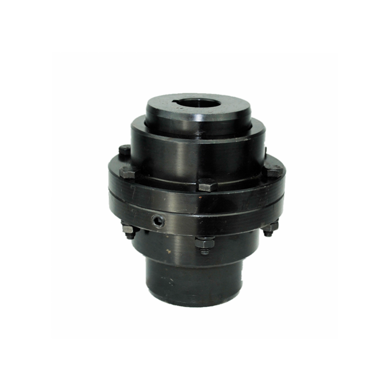
What makes a gear coupling a drum gear coupling is the crowned tooth profile on the hub — the teeth are cut with a curved lengthwise profile that lets the coupling articulate under angular misalignment while keeping tooth contact across the full face width. That articulation depends on clearance: the working clearance between hub tooth flanks and sleeve tooth flanks, designed into the mesh to accommodate angularity and lubrication film.
Excessive clearance in a drum gear coupling produces backlash that shows up as gear rattle under reversing or pulsating load, accelerating tooth flank wear. Insufficient clearance converts the intended rolling-sliding tooth contact into edge loading at the first degree of misalignment, concentrating stress at the tooth crown tip where lubrication is hardest to maintain. The correct clearance is a published value per size, and the specifier's job is to verify the coupling's marked size matches the application's misalignment needs — a coupling that accommodates 2 degrees of angularity spec'd into a machine that actually drifts to 3 degrees is running at zero effective clearance on one side of the mesh.
Bore Tolerance Stack-Up in Assemblies
In a double-engagement drum gear coupling — the standard configuration — two hubs, one sleeve, and two shaft ends stack their tolerances into one system. The axial gap between the hub faces inside the sleeve provides the axial float the coupling needs for thermal growth, and that gap is a function of the assembled lengths, which are themselves tolerance-dependent. A hub machined to the long end of its length tolerance on both ends can consume half the designed axial float before the machine ever warms up.
Fit auditing of an assembly means checking the worst-case stack, not the nominal drawing. Designers who calculate the axial clearance at the tolerance extremes — long hubs, short sleeve, minimum internal shoulder dimensions — find the float they lose to manufacturing variation and can specify the coupling length class accordingly. The same logic applies to the sleeve's internal tooth position relative to the hub crowns: the mesh centers only if the assembly length stack lands on the nominal value.
Installation Consequences of Fit Choices
The fit philosophy a specifier chooses for a drum gear coupling dictates the installation procedure at every maintenance event. An interference-fit hub requires controlled heating — oil bath or induction — to expand the bore enough to slide onto the shaft, and cooling the hub onto the shaft is the alternative for large bores. A clearance-fit hub slides on cold with a light tap, but only after the shaft and bore are verified clean and the key is confirmed to seat without force.
What fails in practice is mixing the two: a clearance-fit hub forced onto an oversized shaft with a sledge, or an interference hub assembled cold because the heater was not available. Both produce hidden damage — a stretched bore, a galled shaft surface, a hub cracked at the keyway root — that does not surface until the coupling is under load. The drawing's tolerance class is also an installation instruction, and it belongs in the maintenance manual in those terms.
Verification Methods for Tolerance Compliance
Receiving inspection is where tolerance and fit problems are cheapest to catch. A bore gauge, a micrometer on the shaft journal, and a calibrated key check take ten minutes per coupling and catch the dimensional drift that a tape measure misses. For critical drives, plants add a runout check of the assembled hub on the shaft — dial indicator on the hub face and diameter — to catch the seated eccentricity that no static dimension reveals.
For high-value or high-speed installations, a full dimensional report from the coupling supplier, certifying bore, keyway, and tooth profile against the drawing, is standard purchasing language. A drum gear coupling with certified dimensions removes the receiving-inspection guesswork and puts the tolerance responsibility where it belongs — on the manufacturer who cut the steel.
Frequently Asked Questions
What is the correct bore fit for a drum gear coupling?
It depends on duty. Interference fits (ISO s6, t6) for shock-loaded and reversing drives; transition or light press fits (k6, h7) for uniform loads where serviceability matters. The torque path differs — interference relies on the fit, transition relies on the key — so the fit class and the keyway spec must be chosen together, not independently.
How much tooth clearance should a drum gear coupling have?
Enough to articulate at the coupling's rated misalignment without edge loading, and no more. The value is published per coupling size. If the application's actual misalignment approaches the rating, check whether the mesh still has working clearance at the tolerance extremes — marginal applications get re-rated or oversized.
Why does my coupling key keep fretting?
Almost always a fit problem: the hub bore is at the clearance end of its tolerance, the keyway slot is wider than the standard class, or the hub is not seating fully on the shaft. Check the bore and keyway against the drawing with calibrated tools; fretting is the symptom, not the cause.
Should I heat an interference-fit hub every time?
Yes. Controlled heating to the specified temperature range expands the bore for a safe slide-on without stretching the hub or galling the shaft. Cold assembly of an interference fit damages the bore, the shaft, or both, and the damage is invisible until the coupling fails under load.
Conclusion
Drum gear coupling tolerance and fit are the quiet determinants of coupling life. The bore tolerance class sets the torque path and the installation procedure; the keyway standard decides whether the key seats and stays; the tooth clearance determines whether articulation lubricates or edge-loads; and the assembly stack decides the axial float a machine needs for thermal growth. Each dimension is a decision recorded in the drawing, and the specifier who treats those numbers as instructions — verified at receiving, respected at installation — is the one whose couplings go on once, run without drama, and come off at the scheduled interval instead of the emergency call.
References
AGMA 9002-B04 — Flexible Couplings: Design Considerations and Selection
ISO 14691:2008 — Flexible Couplings: Design, Selection and Application
ISO 773:2007 — Rectangular or Square Parallel Keys and Their Corresponding Keyways
ISO 286-1:2010 — Geometrical Product Specifications: ISO Code System for Tolerances
API 671 — Special Purpose Couplings for Petroleum, Chemical, and Gas Industry Services