

Industrial power transmission systems frequently encounter sudden torque spikes that can damage connected equipment if the coupling between driver and driven shafts cannot absorb and redistribute these transient loads. The spring grid coupling has earned a well-established reputation across mining, steel processing, crushing, and heavy material handling industries for its exceptional ability to cushion shock loads while maintaining reliable torque transmission under continuous operation.
This article examines the engineering characteristics that make spring grid coupling designs uniquely effective in shock load environments, supported by application data from real industrial installations. Whether you are evaluating coupling options for a new crusher drive, conveyor system, or heavy mill application, understanding the performance advantages of spring grid technology directly informs better specification decisions.
How Spring Grid Coupling Technology Absorbs Shock Loads
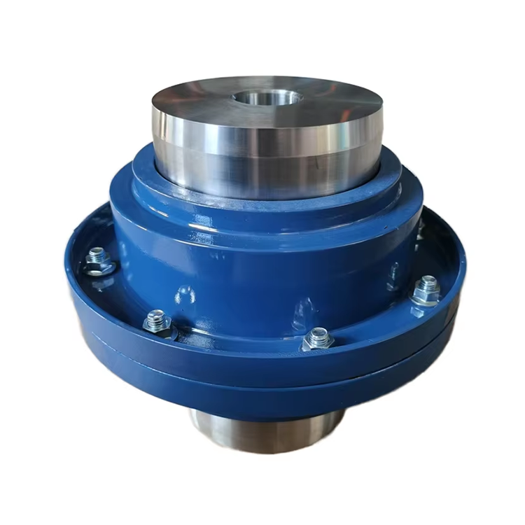
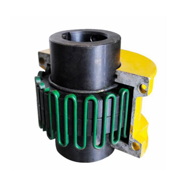
The fundamental mechanism behind shock load absorption in a spring grid coupling is the progressive engagement of the serpentine grid spring within the hub tooth profile. Under steady-state conditions, the grid transmits torque through continuous contact across multiple tooth surfaces. When a sudden torque spike occurs — such as a crusher encountering an uncrushable object or a conveyor experiencing a jam — the grid flexes within the hub profile, progressively engaging additional contact surfaces and distributing the peak load over a wider area.
This progressive torque distribution converts a sharp, high-amplitude shock into a broader, lower-amplitude pulse that the connected equipment can withstand without damage. The time duration of shock load attenuation typically ranges from 10 to 50 milliseconds depending on coupling size and grid spring characteristics, providing sufficient damping to protect motor windings, gearboxes, and bearings from instantaneous over-torque conditions.
Comparative testing conducted by coupling research laboratories demonstrates that spring grid couplings reduce peak transmitted shock torque by 40-60% compared to rigid connections and by 20-30% compared to elastomeric couplings of equivalent torque rating. This performance advantage is particularly significant in applications where shock events occur repeatedly throughout each operating shift.
Torsional Flexibility: Protecting Connected Equipment
Beyond shock absorption, spring grid coupling designs provide inherent torsional flexibility that benefits the entire drivetrain. Torsional stiffness values for grid couplings typically fall between rigid and elastomeric coupling designs, offering a balanced compromise that dampens torsional vibration without introducing excessive wind-up that affects positional accuracy.
In applications involving internal combustion engines, reciprocating compressors, or multi-cylinder pumps, torsional vibration can excite natural frequencies in the drivetrain, causing resonance conditions that dramatically amplify cyclic stresses. The torsional damping provided by grid spring interaction shifts the drivetrain's natural frequency away from excitation sources, reducing vibration amplitudes and extending component fatigue life throughout the machine train.
Engineering analysis of failed drivetrain components frequently reveals that torsional resonance — rather than steady-state overload — was the root cause of bearing and gear failures. Specifying a spring grid coupling with appropriate torsional stiffness for the specific application addresses this often-overlooked failure mechanism at the coupling interface, protecting downstream equipment from destructive vibration energy.
Applications Where Spring Grid Coupling Designs Excel
Mining and mineral processing represent the largest application segment for spring grid coupling technology. Rock crushers, grinding mills, and heavy-duty conveyors routinely encounter sudden load reversals and shock events that demand robust coupling protection. Field data from major mining operations shows that grid couplings in these applications achieve 3 to 5 times longer service life than elastomeric alternatives under equivalent shock loading conditions.
Steel processing and rolling mill drives present similar challenges, with intermittent heavy biting loads during slab reduction passes generating peak torque spikes 2-3 times above nominal operating levels. The spring grid coupling provides the necessary transient overload capacity without requiring oversized coupling specifications that increase cost and rotational inertia.
Pulp and paper processing employs spring grid couplings on debarker drives, chipper feeds, and refiner applications where wood fiber introduces variable loading with frequent shock events. The coupling's ability to operate in environments with moderate moisture exposure — when properly lubricated and sealed — makes it suitable for these demanding process conditions.
High Torque Capacity in a Compact Package
One of the practical advantages of spring grid coupling design is its high torque-to-size ratio. The grid spring's serpentine geometry provides a large torque transmission area within a relatively small envelope diameter. For space-constrained installations — such as underground mining equipment, marine propulsion drives, or retrofit applications where existing foundation dimensions limit coupling size — this compact footprint enables higher power density without major structural modifications.
Typical bore capacity for standard spring grid coupling sizes ranges from 0.75 inches to over 12 inches, with torque ratings from several hundred foot-pounds to well above 1,000,000 foot-pounds in the largest mining-grade configurations. This broad range allows engineers to select appropriate coupling sizes without excessive oversizing that wastes material and increases rotating inertia.
Reduced rotating inertia from properly sized couplings benefits motor starting performance. Lower inertia means shorter acceleration times, reduced motor starting current, and less thermal stress on motor windings during frequent start-stop cycles. In applications with cyclical duty patterns, these starting performance improvements translate directly to lower energy costs and reduced motor maintenance requirements.
Maintenance Advantages and Total Cost of Ownership
From a lifecycle cost perspective, spring grid coupling designs offer compelling economic advantages. The grid spring element serves as the primary wear component and can be replaced independently of the hub assemblies in most designs. This modular maintenance approach reduces spare parts inventory requirements and cuts mean time to repair by 60-70% compared to couplings requiring complete unit replacement upon element failure.
Lubrication requirements, while more demanding than fully enclosed elastomeric designs, remain straightforward compared to gear coupling alternatives. Scheduled grease replenishment at manufacturer-recommended intervals — typically every 3 to 6 months depending on operating conditions — maintains coupling performance without specialized tools or extensive downtime. Many facilities perform coupling lubrication during planned maintenance windows alongside other routine servicing activities, eliminating dedicated coupling maintenance outages.
When lifecycle cost analysis includes initial procurement, planned maintenance labor, spare parts consumption, and avoided unplanned downtime costs, spring grid coupling installations frequently demonstrate 15-25% lower total cost of ownership compared to both rigid and elastomeric coupling alternatives in shock-loaded applications. The economic advantage increases further in remote installations where unplanned failures involve significant mobilization and logistics costs.
Key Specification Considerations for Engineers
Correctly sizing a spring grid coupling for shock load applications requires evaluating both steady-state torque requirements and peak transient loads. Engineers should catalog the maximum expected shock torque magnitude, duration, and frequency based on process characteristics. Most coupling manufacturers provide sizing factors that account for shock severity — typically expressed as a Service Factor multiplier applied to the nominal torque rating.
Speed considerations are equally important. While grid couplings operate effectively at moderate speeds, very high-speed applications above 5,000 RPM may require balanced coupling designs to prevent centrifugal force effects on the grid spring. Centrifugal force can cause the grid to lift partially from the hub tooth profile at high speeds, reducing torque transmission capacity and increasing wear rates.
Environmental conditions — including temperature extremes, moisture exposure, and chemical contamination potential — influence cover seal selection and lubricant specification. Applications in ambient temperatures above 200°F or below -20°F require coupling models with temperature-rated seals and specially formulated lubricants to maintain performance across the full operating range.
Frequently Asked Questions
What makes a spring grid coupling better than an elastomeric coupling for shock loads?
Spring grid couplings provide higher torque density, superior transient overload capacity, and more consistent damping characteristics across temperature ranges compared to elastomeric designs. Elastomeric elements harden at low temperatures and soften at elevated temperatures, altering coupling behavior unpredictably. Grid springs maintain consistent mechanical properties across a wider temperature range, making them more reliable in applications with variable thermal conditions.
How long does a spring grid coupling grid element typically last?
Grid service life depends primarily on load severity, misalignment conditions, and lubrication quality. In well-aligned, properly lubricated installations with moderate shock loading, grid elements typically achieve 2 to 4 years of continuous service. Heavy shock load applications such as primary crushers may require grid replacement every 12 to 18 months. Following the manufacturer's published inspection and replacement intervals optimizes grid life while preventing unplanned failures.
Can a spring grid coupling handle reversing loads?
Yes. Grid couplings transmit torque equally in both directions through symmetrical grid engagement within the hub tooth profile. This bidirectional capability makes them suitable for applications involving frequent forward-reverse operation, such as travel drives on mining equipment, winch systems, and reversing mill stands. However, reversing applications should account for the cumulative fatigue effects of bidirectional loading when estimating grid service life.
What happens if a spring grid coupling is undersized for the application?
An undersized coupling operates near or beyond its rated capacity, accelerating grid wear, reducing shock absorption effectiveness, and increasing the probability of sudden coupling failure. In severe cases, an undersized grid may fracture under peak load, creating a safety hazard from projectile fragments. Always specify couplings with appropriate service factor margins — typically 1.5 to 2.5 times nominal torque for shock-loaded applications — as recommended by the coupling manufacturer.
Is special alignment required when installing a spring grid coupling?
Standard precision shaft alignment procedures apply — the same laser alignment methodology used for other coupling types. While grid couplings tolerate moderate misalignment, operating within the manufacturer's rated misalignment limits is essential for achieving rated grid service life. A properly aligned grid coupling delivers maximum shock absorption performance and the longest possible interval between maintenance interventions.
Conclusion
The spring grid coupling provides a proven engineering solution for industrial power transmission systems facing repetitive shock loads, variable torque demands, and demanding operating environments. Its unique combination of progressive torque distribution, torsional flexibility, high power density, and modular maintainability delivers measurable reliability and economic advantages across mining, steel processing, pulp and paper, and heavy material handling applications. By understanding the performance characteristics described in this guide and applying correct specification practices, engineers can confidently select spring grid coupling technology to protect critical drivetrain equipment while minimizing total ownership costs across the equipment lifecycle.
References
AGMA 9002-B04 — Flexible Couplings: Design Considerations and Selection
ISO 14691:2008 — Flexible Couplings: Design, Selection and Application
Sekhar, R.S. & Prasad, B.S. (2015). "Dynamic Analysis of Grid Couplings Under Shock Loading Conditions." International Journal of Rotating Machinery, 2015, 1-12.
API 671 — Special Purpose Couplings for Petroleum, Chemical, and Gas Services
Mancuso, J.R. (1999). Couplings and Joints: Design, Selection, and Application, 2nd Edition. Marcel Dekker.