

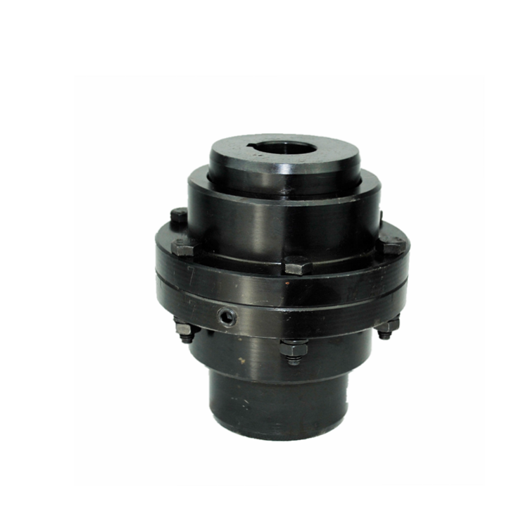
The specification sheet for a drum gear coupling contains the technical data that defines its capabilities, limitations, and application suitability. However, these specifications are only useful to engineers and procurement professionals who can interpret them correctly. Misreading a torque rating, overlooking a speed limitation, or ignoring a material specification can lead to coupling failures that cost far more than the coupling itself. Understanding what each specification parameter means — and how it relates to actual operating conditions — transforms a specification sheet from a confusing table into a reliable selection tool.
This reference explains the key specification parameters found on drum gear coupling data sheets, providing the context and practical interpretation that supports confident specification decisions for industrial power transmission applications.
Torque Ratings: Continuous vs. Peak Capacity
Torque rating is the primary selection parameter for any drum gear coupling, yet it is frequently misunderstood. The continuous torque rating specifies the maximum torque the coupling can transmit indefinitely without exceeding the material fatigue limit of the gear teeth. This rating assumes uniform loading, proper lubrication, and alignment within rated limits. Real-world applications with variable loads require applying service factors that effectively increase the required torque capacity.
Peak torque rating — typically 2 to 3 times the continuous rating — specifies the maximum short-duration torque the coupling can withstand without permanent deformation or tooth damage. Peak ratings apply to transient events — startup surges, temporary overloads, and emergency conditions — lasting no more than a few seconds per occurrence. Repeated operation at or near the peak rating reduces service life even if individual events remain within the peak capacity.
Torque ratings are expressed in units of Newton-meters (Nm) or pound-feet (lb-ft) and are typically listed for each coupling size at a reference speed. Many drum gear coupling specifications also include a torque per inch of face width value that allows engineers to evaluate coupling capacity relative to the available tooth engagement area — a useful comparison metric when evaluating different coupling designs for the same bore size.
The rating basis must be verified — some manufacturers rate couplings for infinite life at rated torque, while others base ratings on a specific number of load cycles (typically 10 million for industrial applications). Understanding which basis applies prevents overestimating coupling capacity and selecting a coupling too small for the application.
Misalignment Capacity Specifications and Interpretation
Misalignment specifications for a drum gear coupling typically list three values: angular misalignment per flex plane (in degrees), parallel offset (in inches or millimeters), and axial displacement (in inches or millimeters). These values represent the maximum misalignment the coupling can accommodate while maintaining rated torque capacity — operating beyond these limits reduces both torque capacity and service life.
Angular misalignment ratings for drum gear couplings typically range from 0.5° to 1.5° per flex plane, depending on coupling size and tooth profile design. The crowned tooth profile that characterizes drum gear couplings provides superior angular misalignment capacity compared to straight-tooth designs. However, these ratings assume the misalignment is within a single plane — compound misalignment (angular in multiple planes combined with parallel offset) reduces the effective capacity in each plane.
Parallel offset specifications range from 0.005 to 0.060 inches for standard industrial sizes. This value represents the maximum lateral displacement between shaft centerlines that the coupling can accommodate at rated torque and speed. Operating at maximum parallel offset combined with maximum angular misalignment simultaneously may exceed the coupling's combined misalignment capacity — always consult manufacturer guidelines for combined misalignment conditions.
Axial displacement capacity — the coupling's ability to accommodate shaft end movement from thermal expansion or axial float — typically ranges from 0.020 to 0.125 inches for standard couplings. Axial capacity is influenced by the clearance between hub end faces and the available space within the coupling sleeve. Applications with significant thermal growth require verification that axial capacity exceeds the expected shaft movement.
Speed Ratings and Balance Grades
Maximum speed rating for a drum gear coupling is determined by centrifugal force effects on the sleeve and gear teeth, lubrication retention at high speeds, and balance limitations. Standard couplings without special balance specifications are typically rated for speeds up to 3,600-5,000 RPM. Higher-speed applications require precision-balanced couplings that reduce the centrifugal unbalance forces that increase with the square of rotational speed.
Balance grade specifications follow ISO 21940 standards, with G6.3 as the standard balance quality for industrial drum gear couplings at speeds below 3,600 RPM. Higher speeds require G2.5 or G1.0 balance grades achieved through precision machining, material removal, or addition of correction weights. The balance grade specification directly affects coupling vibration levels and bearing loads — under-specifying balance quality for high-speed applications produces vibration that damages both the coupling and connected equipment.
High-speed coupling designs may incorporate additional features not found in standard specifications — including reduced-clearance sleeve retention, labyrinth seals that function effectively at high RPM, and specialized lubrication systems that maintain tooth surface coverage despite centrifugal grease displacement. These features should be specified when operating speeds exceed 3,600 RPM or when the coupling diameter produces surface speeds above approximately 50 feet per second.
Material Specifications and Heat Treatment Requirements
Hub material specifications for drum gear coupling components define the mechanical properties that determine torque capacity and service life. Common hub materials include AISI 4140 (chromium-molybdenum alloy steel), 42CrMo4 (European standard equivalent), and 1045 (medium carbon steel). Material selection depends on the required strength, hardness, and toughness balance for the specific application.
Heat treatment specifications are as important as the base material grade. Through-hardened hubs — typically hardened to 32-48 HRC — provide good strength and wear resistance for standard applications. Case-hardened hubs — carburized to a case depth of 0.030-0.060 inches with core hardness of 28-35 HRC — provide superior surface wear resistance combined with tough cores that resist impact damage. The heat treatment specification must be matched to the application's load characteristics and environmental conditions.
Surface hardness specifications for tooth contact surfaces typically range from 50-60 HRC for hardened steel teeth. Higher hardness improves wear resistance but reduces impact toughness — a tradeoff that must be evaluated for shock-loaded applications. Coupling manufacturers provide hardness specifications matched to their tooth profile design and intended service conditions. Substituting alternative hardness specifications without engineering analysis risks either accelerated wear or brittle tooth fracture.
Bore Range and Keyway Specifications
Bore range specifications define the minimum and maximum shaft diameters the coupling hub can accommodate. The bore range is determined by hub wall thickness requirements — the maximum bore leaves adequate wall thickness for strength, while the minimum bore uses the hub material efficiently without excessive machining. Bearing this range in mind during shaft design ensures compatibility with standard coupling sizes.
Standard bore sizes are typically available in 1mm or 1/16-inch increments within the coupling's bore range. Custom bore sizes — between standard increments or with special tolerances — are available from most manufacturers at additional cost and lead time. For critical applications, specifying bore dimensions to match actual shaft measurements rather than nominal shaft diameters ensures proper fit control.
Keyway specifications follow DIN 6885 (metric) or ANSI B17.1 (inch) standards for parallel keys. The specification includes key width, height, and depth dimensions matched to the bore diameter. Keyway tolerance controls the side fit between the key and keyway — typically JS9 for metric applications — which determines how tightly the key seats within the hub keyway slot during torque transmission.
Lubrication and Seal Specifications
Lubrication specifications for drum gear coupling service are frequently underappreciated during coupling selection despite their direct impact on service life. The specification includes lubricant type, viscosity grade, fill quantity, and replenishment interval — all tailored to the coupling size, operating speed, and environmental conditions. Using non-specified lubricants or extending lubrication intervals beyond recommendations accelerates tooth wear and reduces coupling life.
Seal specifications define the coupling's environmental protection capabilities. Standard labyrinth seals provide adequate protection for indoor, relatively clean environments. Contact seals — lip seals or O-ring configurations — provide superior protection against fine dust and moisture ingress for outdoor or contaminated environments. Specialized seals for washdown environments, high-temperature service, or chemical exposure are available from major coupling manufacturers.
Operating temperature range specifications define the ambient conditions within which the coupling maintains rated performance. Standard designs operate from -20°F to 250°F. Extended-range designs extend this to -65°F or +400°F through appropriate seal and lubricant selection. Applications operating outside the standard temperature range require coupling models with verified performance at the actual operating temperatures.
Frequently Asked Questions
How do I select the correct drum gear coupling size from specifications?
Begin with the application's continuous torque requirement, apply the appropriate service factor based on load characteristics (1.0-3.0 depending on shock loading), select a coupling size with torque rating exceeding the adjusted requirement, then verify the selected size meets speed, misalignment, and bore requirements. Always cross-reference multiple parameters — a coupling with adequate torque but insufficient speed rating will fail prematurely.
What does "continuous rating" mean in coupling specifications?
Continuous rating defines the maximum torque the coupling can transmit indefinitely under uniform loading conditions without exceeding design fatigue limits. This rating assumes proper installation, alignment within rated limits, and specified lubrication at recommended intervals. Operating continuously beyond the continuous rating accelerates fatigue damage and reduces coupling service life on a progressive basis.
Can I exceed the rated speed on a drum gear coupling short-term?
Exceeding rated speed, even briefly, is not recommended. Centrifugal forces increase with the square of speed, meaning a 10% overspeed increases centrifugal loads by 21%. These loads affect sleeve retention, seal contact pressure, and lubrication distribution. Unlike torque overloads where short-duration peaks may be tolerable, speed excursions create conditions that can lead to immediate coupling damage.
How do I verify that a drum gear coupling meets its published specifications?
Request material test certificates for hub and sleeve materials, dimensional inspection reports for bore and keyway dimensions, and balance certificates where applicable. Reputable coupling manufacturers provide this documentation as part of standard quality assurance. Third-party inspection services can verify coupling conformance to specifications when required for critical applications.
Conclusion
Drum gear coupling specifications provide the technical foundation for matching coupling capabilities to application requirements. Understanding torque ratings, misalignment capacities, speed limits, material specifications, bore ranges, and lubrication requirements enables engineers to select couplings that deliver reliable service across demanding industrial applications. The time invested in correctly interpreting specification parameters prevents the costly failures that result from selection errors and ensures that the coupling specified is the coupling needed for reliable, long-service-life power transmission.
References
AGMA 9002-B04 — Flexible Couplings: Design Considerations and Selection
ISO 14691:2008 — Flexible Couplings: Design, Selection and Application
DIN 6885 — Drive Type Fastenings Without Taper Action
API 671 — Special Purpose Couplings for Petroleum, Chemical, and Gas Industry Services
ISO 21940-11:2016 — Mechanical Vibration: Rotor Balancing