

In industrial rotating machinery, the coupling between motor and driven equipment functions as the critical link that transmits torque while accommodating the inevitable misalignment and dynamic loads inherent in real-world installations. Understanding coupling performance characteristics — including torque capacity, misalignment compensation, torsional stiffness, and damping behavior — allows engineers to make specification decisions that maximize equipment uptime and minimize lifecycle costs.
This technical overview examines the primary performance parameters that govern coupling behavior in rotating systems, drawing on established engineering principles and field experience from process industries, power generation, mining, and heavy manufacturing applications. Whether you are designing a new drivetrain or evaluating an existing installation, these performance fundamentals provide the foundation for sound engineering decisions.
Torque Transmission Capacity: The Foundation of Coupling Performance
The most fundamental performance metric for any coupling is its torque transmission rating. This rating defines the maximum continuous torque the coupling can reliably transmit without exceeding design stress limits in the flexible element or connection hardware. Torque ratings are expressed in units of Newton-meters (Nm) or pound-feet (lb-ft), with published values typically based on steady-state operation at rated speed.
However, real-world coupling performance depends on much more than the catalog torque number. Engineers must evaluate peak torque events — including startup transients, load reversals, and shock loads — that may exceed nominal operating torque by 150-300%. Selecting a coupling based solely on nameplate motor torque without accounting for these transients frequently leads to premature failures that could have been prevented with proper sizing.
Service factor selection bridges the gap between nominal and actual operating conditions. Industrial applications typically require service factors ranging from 1.0 for uniform loads such as centrifugal fans, to 2.5 or higher for heavy shock loading in crushers, hammer mills, and reciprocating compressors. The American Gear Manufacturers Association (AGMA) publishes application-specific service factor tables that provide engineering guidance for coupling sizing across hundreds of equipment types.
Misalignment Compensation and Dynamic Behavior
Misalignment tolerance represents the coupling's ability to operate reliably when the connected shafts are not perfectly collinear. All industrial couplings accommodate some degree of angular, parallel, and axial misalignment — but the mechanism and magnitude of compensation varies significantly across coupling types. Flexible element couplings rely on controlled flexing of elastomeric, metallic, or composite elements to accommodate misalignment while transmitting torque.
Dynamic misalignment — the change in shaft alignment between static and operating conditions — adds complexity that static alignment specifications do not fully capture. Thermal expansion, foundation deflection under load, and pipe strain introduce operating misalignment that frequently exceeds cold-alignment measurements by 30-50%. A coupling with generous static misalignment ratings provides a safety margin against these dynamic variations.
Operating a coupling at or near its maximum rated misalignment capacity significantly accelerates flexible element fatigue. Engineering best practice targets continuous operation at no more than 50-60% of the coupling's published misalignment rating, reserving the remaining capacity for transient conditions and alignment drift over time.
Torsional Stiffness and Vibration Characteristics
Torsional stiffness — the resistance of the coupling to angular deflection under applied torque — directly influences the dynamic behavior of the entire machine train. High-stiffness couplings transmit torsional vibration with minimal damping, while lower-stiffness designs absorb energy and reduce vibration transmission to connected equipment. Selecting the appropriate torsional stiffness requires understanding the system's natural frequencies and the excitation sources present in the application.
Torsional vibration analysis becomes critical when the driving source contains significant cyclic torque variation — such as internal combustion engines, reciprocating compressors, or multi-cylinder pumps. If the coupling stiffness places the system's natural frequency near an excitation frequency, resonance amplifies vibration amplitudes, potentially causing rapid fatigue failures in shafts, bearings, and coupling elements.
Engineers use torsional stiffness data from coupling manufacturers to build lumped-parameter system models that identify natural frequencies and predict vibration response. These analyses guide coupling selection that avoids resonance zones and provides adequate damping across the operating speed range.
Speed and Temperature Effects on Performance
Operating speed influences coupling performance through centrifugal force effects on the flexible element and increased cyclic loading frequency. High-speed applications — above 4,000 RPM for many coupling types — require balanced designs and reduced misalignment ratings to prevent centrifugal force from distorting the flexible element or causing unstable operation.
Temperature affects both the coupling's mechanical properties and the performance of lubricants or seal materials in enclosed designs. Elastomeric elements experience significant stiffness changes with temperature: hardness increases at low temperatures, reducing misalignment accommodation, while elevated temperatures soften the material, decreasing torque capacity. Metallic flexible couplings maintain more consistent performance across temperature ranges, making them preferable for applications with wide thermal variations.
Most manufacturers provide temperature derating curves that specify the percentage of rated capacity available at various operating temperatures. Operating a coupling beyond its rated temperature range without applying derating factors accelerates element degradation and creates unpredictable failure risk.
Balancing Requirements for High-Speed Applications
Rotational imbalance in a coupling generates vibration forces proportional to the square of rotational speed. While low-speed applications tolerate modest imbalance without noticeable effects, high-speed installations require carefully balanced couplings to prevent excessive vibration and bearing loads. Balance quality grades per ISO 21940 define permissible residual imbalance based on coupling mass and maximum operating speed.
Most quality coupling suppliers provide standard balance grades suitable for applications up to 3,600 RPM. Higher-speed applications — such as turbine generators, high-speed compressors, and precision machine tools — require enhanced balance specifications achieved through precision machining, material removal, or addition of balance correction weights.
Field balancing may be necessary after installation to account for residual imbalance from associated components, shaft runout, and assembly tolerances. Vibration signature analysis during commissioning identifies imbalance-related vibration at 1X running frequency, guiding correction efforts.
Performance Monitoring and Condition Assessment
Continuous performance monitoring enables condition-based maintenance strategies that optimize coupling service life while preventing unplanned failures. Vibration analysis provides the primary diagnostic tool, with characteristic frequency patterns indicating specific failure modes: increases at 1X frequency suggest imbalance or misalignment, while harmonics at 2X, 3X, and higher multiples indicate mechanical looseness or flexible element deterioration.
Thermographic inspection identifies abnormal heat generation from friction, misalignment, or lubrication breakdown. Operating temperatures exceeding the coupling's rated range signal a need for investigation and probable intervention. Many facilities have incorporated coupling temperature monitoring into their predictive maintenance programs as a low-cost, high-value indicator of developing problems.
Frequently Asked Questions
How do I determine the correct service factor for my coupling application?
Service factor selection depends on the driven equipment type, load profile, and operating conditions. AGMA publishes detailed tables matching equipment categories to recommended service factors. For applications with frequent starts, reverse operation, or significant shock loading, use the higher end of the recommended range. When in doubt, consult the coupling manufacturer's application engineering team for guidance specific to your operating conditions.
What happens if I operate a coupling above its rated speed?
Exceeding rated speed increases centrifugal forces on the flexible element, potentially causing distortion, accelerated wear, or mechanical failure. Most manufacturers provide maximum speed ratings that include appropriate safety margins. Operating even slightly above rated speed can invalidate warranty coverage and create safety hazards. Always verify that the coupling's maximum rated speed exceeds the actual operating speed with adequate margin.
Can coupling performance change over time?
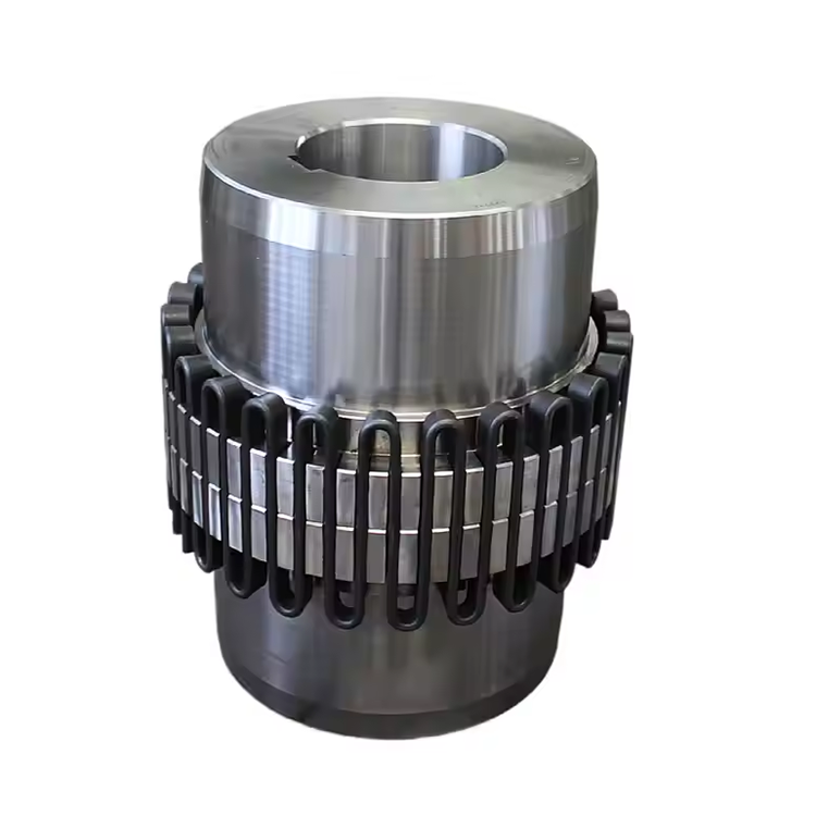
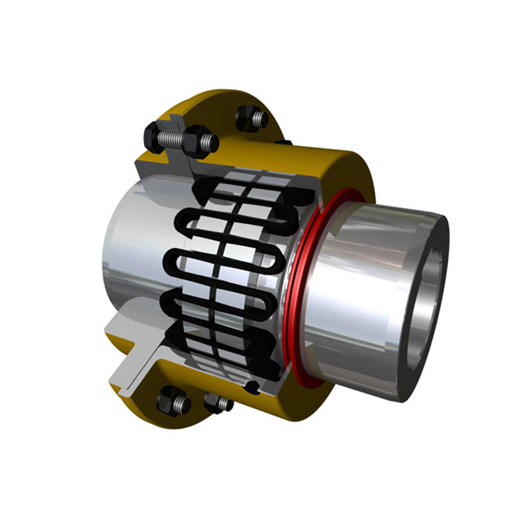
Yes. Flexible element degradation, lubrication breakdown, and alignment drift all progressively reduce coupling performance. Elastomeric elements harden with age and thermal cycling, decreasing misalignment accommodation. Worn grid elements develop increased backlash, reducing shock absorption effectiveness. Periodic performance verification through vibration analysis and visual inspection identifies these changes before they lead to failures.
How does ambient temperature affect coupling selection?
Ambient temperature influences both coupling material properties and lubricant behavior. For extreme cold environments below -20°F, elastomeric couplings may stiffen beyond usable limits, requiring metallic flexible alternatives. High-temperature environments above 200°F degrade standard elastomers and greases, necessitating heat-resistant materials and lubricants. Always specify the full temperature range — including startup and shutdown transients — when selecting a coupling.
What role does the coupling play in system torsional natural frequency?
The coupling's torsional stiffness directly affects the system's lowest torsional natural frequency. Selecting a coupling with appropriate stiffness avoids resonance with excitation frequencies from the driver or driven equipment. Torsional analysis software and coupling manufacturer engineering support help identify safe stiffness ranges for each application. Incorrect coupling stiffness can place a natural frequency within the operating speed range, leading to destructive resonance.
Conclusion
Coupling performance in rotating systems depends on the integrated evaluation of torque capacity, misalignment tolerance, torsional characteristics, speed and temperature effects, and dynamic balance. Each parameter interacts with the others, creating a system-level behavior that cannot be predicted from any single specification alone. Engineers who consider these interrelated factors — and verify performance through monitoring programs — consistently achieve superior equipment reliability and lower lifecycle costs compared to those relying on simplified catalog-based selection methods.
References
AGMA 9002-B04 — Flexible Couplings: Design Considerations and Selection
ISO 14691:2008 — Flexible Couplings: Design, Selection and Application
Api 671 — Special Purpose Couplings for Petroleum, Chemical, and Gas Industry Services
Mancuso, J.R. (1999). Couplings and Joints: Design, Selection, and Application, 2nd Edition. Marcel Dekker.
ISO 21940-11:2016 — Mechanical Vibration: Rotor Balancing