

The shaft connection interface between a drum gear coupling and the connected equipment represents one of the most critical aspects of power transmission system design. A perfectly manufactured coupling delivers poor performance if the shaft connection is improperly specified or poorly installed. Understanding the connection methods, fit tolerances, and retention mechanisms available for drum gear coupling assemblies enables engineers to ensure reliable torque transmission while accommodating the practical demands of installation and maintenance.
This technical guide covers the fundamental principles of shaft connection for drum gear couplings, addressing hub mounting methods, keyway specifications, interference fits, and the field practices that distinguish reliable installations from those prone to premature failure.
Hub Mounting Methods for Drum Gear Coupling Assemblies
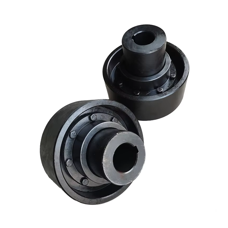
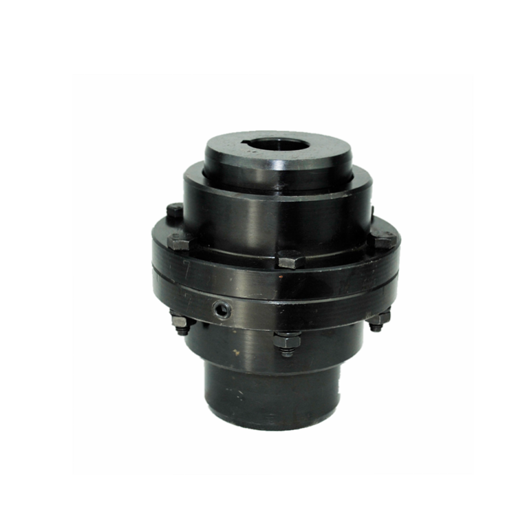
Drum gear coupling hubs connect to shafts through several well-established mounting methods, each suited to specific application requirements. The most common approach uses a clearance fit with a keyway — the hub bore matches the shaft diameter within a defined tolerance class, and a parallel or taper key transmits torque between shaft and hub. This method provides straightforward installation and removal, making it the default choice for most industrial drum gear coupling applications.
Taper bore mounting offers enhanced torque transmission capability for high-demand applications. The hub bore features a tapered profile that matches a taper on the shaft end. As the hub is pushed onto the taper, radial expansion creates an interference fit that supplements key-driven torque transmission. This approach eliminates bore clearance that can lead to fretting wear under cyclic loading, extending connection life in heavy-duty service.
Shrink fit mounting provides the highest torque transmission capacity for critical applications where maximum connection reliability is required. The hub bore is machined slightly undersized relative to the shaft, then heated to expand the bore before assembly. Upon cooling, the hub contracts around the shaft, generating substantial radial pressure that transmits torque through friction alone — often without requiring a key. This method demands precise thermal control during installation but delivers virtually zero-backlash connections.
Keyway Specifications and Standards
Keyway dimensions for drum gear coupling hub connections follow established international standards. ANSI B17.1 defines parallel key dimensions and tolerances for inch-system applications, while DIN 6885 covers metric key specifications. Both standards provide key width, height, and depth values matched to shaft diameter ranges, ensuring interchangeability between coupling manufacturers and shaft suppliers.
Key selection depends on the torque transmission requirement and the available hub wall thickness. Standard square keys — where key width equals key height — serve most general-purpose applications. Rectangular keys with width exceeding height provide deeper engagement in the shaft keyway while maintaining adequate hub wall thickness, preferred for larger bore sizes and higher torque ratings.
Keyway manufacturing quality directly affects connection performance and service life. Keyways machined with excessive undercut or burrs create stress concentrations that initiate fatigue cracks in the shaft or hub. Keyway walls should be finished to 63 microinches Ra or better for critical applications. Width and depth tolerances must conform to standard specifications — oversized keys forced into undersized keyways create hub expansion stress that reduces fit integrity.
Shaft Fit Tolerances and Their Impact on Performance
Shaft-to-hub fit tolerance determines whether the connection operates with clearance, transition, or interference conditions during service. Clearance fits — where the hub bore slightly exceeds the shaft diameter — provide easy assembly and disassembly but allow relative motion between hub and shaft under torsional loading. This motion, though microscopic, causes fretting wear at the interface that progressively enlarges the bore and reduces torque transmission reliability.
Transition fits occupy the middle ground, where assembled components may exhibit slight clearance or slight interference depending on where individual dimensions fall within their tolerance ranges. These fits provide a reasonable compromise between assembly convenience and connection security for moderate-duty applications.
Interference fits — where the hub bore is smaller than the shaft diameter — create radial pressure at the interface that transmits torque through friction and eliminates relative motion. The magnitude of interference determines the friction force available for torque transmission. Typical interference values range from 0.0005 to 0.002 inches per inch of bore diameter, depending on hub material, wall thickness, and assembly method.
Retention Mechanisms: Preventing Axial Movement
Axial retention mechanisms prevent the drum gear coupling hub from sliding off the shaft during operation. Shaft shoulder abutment provides the simplest retention method — the hub seats against a machined shoulder on the shaft that defines axial position and resists axial thrust loads transmitted through the coupling.
Locking nuts and washers offer adjustable axial retention for applications where precise hub positioning is required. A threaded nut screwed onto the shaft end bears against a hardened washer seated in the hub face, securing axial position while allowing adjustment during assembly. Thread-locking compounds prevent nut loosening from vibration during operation.
Set screws provide supplementary retention in clearance-fit applications. Positioned at 90 degrees to the keyway and tightened against the shaft, set screws resist axial movement of the hub. While commonly used, set screws alone do not provide sufficient retention for heavy-duty applications — they should supplement shoulder abutment or locking nut systems rather than serve as the primary retention mechanism.
End plates bolted to the hub face offer robust retention for large-bore applications where nut-based systems become impractical. The end plate clamps the hub axially against the shaft shoulder while distributing retention force across a large surface area. Bolt torque specifications for end plate fasteners must be followed carefully to ensure adequate retention without exceeding hub material yield strength.
Installation Best Practices for Reliable Connections
Proper installation procedures directly determine the quality of the shaft-to-coupling connection. Before assembly, clean both shaft and hub bore surfaces thoroughly to remove oil, debris, and corrosion products. Even thin films of contamination prevent proper seating and reduce the effectiveness of interference fits. Precision measuring instruments — micrometers, bore gauges, and dial indicators — verify that shaft and bore dimensions fall within specified tolerances before assembly.
Hub installation requires controlled axial positioning to ensure proper engagement without damage. Forcing a hub onto a shaft using hammer blows on the hub exterior introduces contamination risks and may damage bearing surfaces or distortion in the hub wall. Hydraulic press installation or thermal expansion methods provide controlled, repeatable assembly that protects component surfaces.
Thermal installation for interference-fit hubs requires careful temperature control. Heating the hub to 250-400°F (120-200°C) in an oil bath or controlled furnace provides adequate bore expansion for assembly without affecting material properties. Temperature monitoring with calibrated instruments prevents overheating that could alter the hub's metallurgical structure. Hub temperature should never exceed 600°F for standard alloy steel components.
After assembly, verify axial position against the shaft shoulder or specified dimension using depth gauges or calipers. Check key seating by attempting slight rotational movement — properly fitted keys prevent perceptible movement at the hub-shaft interface. Document installation measurements for future reference during maintenance inspections.
Alignment Considerations After Shaft Connection
Shaft connection and coupling alignment are interrelated processes that must be coordinated during installation. Hub mounting affects shaft end position and runout, which in turn influence alignment measurements. Install both coupling halves on their respective shafts before conducting precision alignment measurements to ensure that mounting-induced runout is captured in the alignment data.
Hub face runout — the deviation of the hub mounting face from perpendicularity with the shaft centerline — introduces coupling misalignment even when shaft centerlines are perfectly aligned. Runout tolerances of 0.001 inches total indicator reading (TIR) are typical for industrial drum gear coupling installations. Higher runout values indicate shaft straightness issues, hub mounting problems, or manufacturing defects requiring correction.
Laser alignment measurements should be taken at the coupling flange faces after hub installation is complete. The alignment system measures angular and offset misalignment at the actual coupling interface — not at theoretical shaft centerlines — providing the most relevant data for achieving proper coupling operating conditions.
Troubleshooting Shaft Connection Issues
Hub slippage on the shaft indicates insufficient interference or failed retention mechanisms. The symptom typically manifests as increased vibration at 1X frequency, visible axial movement during inspection, or scoring marks on the shaft surface beneath the hub bore. Root causes include undersized interference, overtightened hub that exceeded material yield strength and relaxed, or fatigue failure of key or retention hardware.
Key damage — sheared, crushed, or deformed keys — results from overload conditions exceeding the connection's torque transmission capacity. If key damage recurs repeatedly despite correct sizing, the root cause likely involves torsional vibration or shock loading exceeding the coupling's design envelope. Torsional analysis and potential coupling reselection become necessary.
Fretting corrosion at the hub-bore interface produces a characteristic reddish-brown powder composed of iron oxide particles. While visually alarming, fretting is a predictable consequence of clearance-fit connections under cyclic torsional loading. Transitioning to interference-fit mounting eliminates fretting by preventing relative motion between hub and shaft surfaces.
Frequently Asked Questions
What is the best shaft connection method for a drum gear coupling?
For general industrial applications, a clearance fit with parallel key provides excellent balance of performance, installation convenience, and maintenance accessibility. For high-torque or high-vibration applications, taper bore mounting with key supplementation delivers superior connection security. Critical applications demanding maximum reliability benefit from shrink-fit mounting with hydraulic nut systems that provide controlled, repeatable interference force.
How do I prevent hub slippage during operation?
Ensure proper interference fit between shaft and hub bore, use correctly sized keys per ANSI B17.1 or DIN 6885 standards, and maintain secure axial retention through shaft shoulders, locking nuts, or end plates. If slippage occurs in a previously stable installation, inspect for shaft wear, hub bore enlargement, and retention hardware fatigue. Address the root cause rather than simply re-torquing fasteners, which provides only temporary correction.
Can I install a drum gear coupling hub without heating?
Yes, for clearance and transition fit applications where the hub bore is larger than or equal to the shaft diameter. Cold assembly using press fitting or manual sliding is standard practice for these fit classes. However, interference-fit hubs require either thermal expansion, hydraulic nut assistance, or mechanical press installation. Attempting cold assembly of interference fits risks component damage and incorrect seating depth.
How tight should key fits be in a drum gear coupling hub?
Key side fit should be transition to light interference — the key should require light tapping with a brass or aluminum drift to seat in the hub keyway. Excessive side clearance allows key rocking under torsional loading, accelerating wear and reducing torque transmission. Key height fit allows the key to project slightly above the shaft keyway to engage the hub keyway with full contact across the key top surface.
What maintenance does a drum gear coupling shaft connection require?
Periodic inspection during scheduled outages should include checking hub position on the shaft for axial drift, verifying set screw or locking nut tightness, inspecting visible keyway edges for wear or deformation, and checking hub bore for signs of fretting or corrosion. Many facilities incorporate hub-to-shaft connection inspection into their coupling maintenance checklist alongside lubrication and cover inspection activities.
Conclusion
The shaft connection between a drum gear coupling and connected equipment determines whether the coupling transmits torque reliably or becomes a recurring source of vibration, wear, and unplanned failures. Proper specification of mounting methods, fit tolerances, keyway dimensions, and retention mechanisms — combined with disciplined installation practices and periodic inspection — transforms the shaft connection from a potential failure point into a robust, long-service-life interface. Engineers and maintenance professionals who apply these principles consistently achieve superior drivetrain reliability and reduced maintenance costs across the full range of industrial drum gear coupling applications.
References
AGMA 9002-B04 — Flexible Couplings: Design Considerations and Selection
ANSI B17.1 — Keys and Keyways
DIN 6885 — Drive Type Fastenings Without Taper Action
ISO 14691:2008 — Flexible Couplings: Design, Selection and Application
Shigley, J.E. et al. (2020). Shigley's Mechanical Engineering Design, 12th Edition. McGraw-Hill.