

Selecting the right coupling for industrial power transmission applications requires more than matching horsepower and speed. Coupling specifications contain critical technical data that determine whether a coupling will perform reliably or fail prematurely in service. For engineers, procurement specialists, and maintenance professionals, understanding how to interpret these specifications is essential for making informed purchasing decisions that optimize equipment reliability and total cost of ownership.
This guide explains the key parameters found in coupling specification sheets, translating technical data into practical selection criteria. Whether you are specifying couplings for a new installation or evaluating alternatives for an existing application, mastering these specification elements enables confident, technically sound decisions.
Why Coupling Specifications Matter in Industrial Applications
Coupling specifications serve as the technical foundation for matching coupling capabilities to application demands. Every industrial coupling must accommodate torque transmission, misalignment, thermal expansion, and dynamic loads — but the magnitude of these requirements varies dramatically across applications. A coupling that performs flawlessly in a centrifugal pump application may fail within weeks if installed on a reciprocating compressor with similar horsepower but very different load characteristics.
The consequences of misinterpreting coupling specifications extend beyond the coupling itself. An underspecified coupling fails prematurely, causing unplanned downtime, potential damage to connected equipment, and safety risks to personnel. An overspecified coupling increases initial cost, adds unnecessary rotating inertia, and may introduce alignment challenges due to larger physical dimensions. Proper specification interpretation balances performance requirements with economic considerations.
Industry data indicates that coupling-related failures account for approximately 15-20% of rotating equipment breakdowns in process industries. A significant percentage of these failures trace back to specification errors — either incorrect parameter interpretation or failure to account for application-specific factors not fully captured in standard specification sheets. Understanding specifications thoroughly helps avoid these costly mistakes.
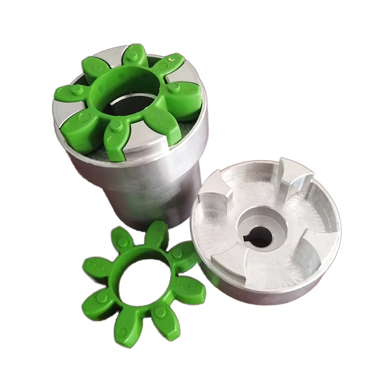
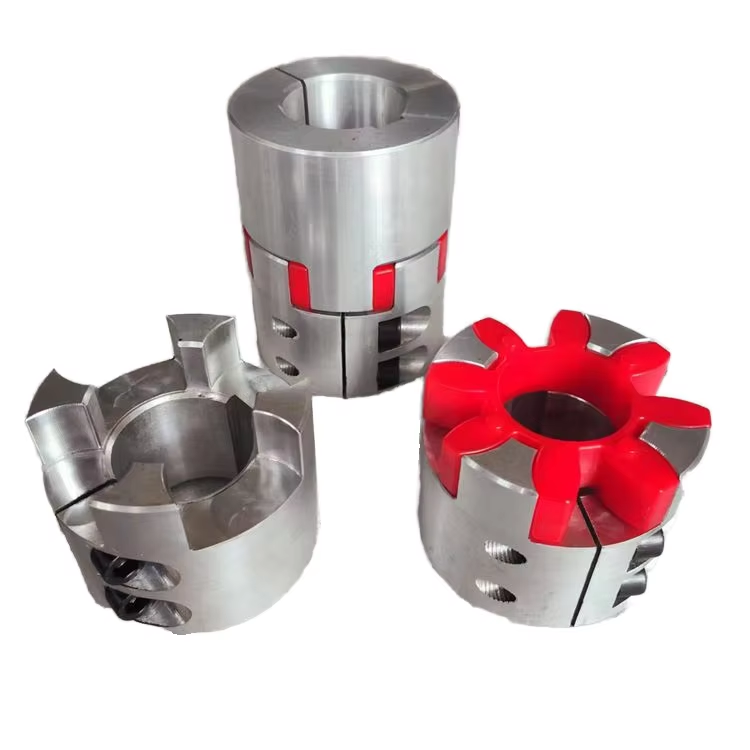
Key Parameters in Coupling Specifications
Every coupling specification sheet contains a core set of parameters that define the coupling's capabilities. Torque rating represents the maximum continuous torque the coupling can transmit without exceeding design stress limits. This value forms the primary selection criterion, but it must be evaluated alongside service factor requirements that account for load variability, starting torque, and operating environment.
Speed rating defines the maximum rotational speed at which the coupling can operate safely. Speed limitations arise from centrifugal force effects on flexible elements, balance considerations, and lubrication requirements. Operating a coupling above its rated speed risks catastrophic failure from element disintegration or excessive vibration.
Misalignment capacity specifies the maximum angular, parallel, and axial misalignment the coupling can accommodate while maintaining rated service life. These values are not suggestions — operating beyond specified misalignment limits accelerates flexible element fatigue and reduces coupling life exponentially. Proper shaft alignment remains essential even with flexible couplings.
Bore size range indicates the minimum and maximum shaft diameters the coupling can accommodate. Hub bore specifications include both standard and custom options, with keyway dimensions and tolerance classes specified according to international standards such as DIN 6885 or ANSI B17.1.
Torque Capacity and Service Factors
Torque capacity specification requires careful interpretation because published ratings assume specific operating conditions. Most coupling manufacturers base torque ratings on uniform load conditions with minimal starting torque and no shock loading. Real-world applications rarely match these ideal conditions, necessitating the application of service factors that adjust the effective torque requirement upward.
Service factor selection follows established industry guidelines such as those published by AGMA (American Gear Manufacturers Association) and ISO. These factors account for load characteristics (uniform, moderate shock, heavy shock), starting frequency, operating hours per day, and environmental conditions. A centrifugal pump with smooth operation might require a service factor of 1.0-1.3, while a rock crusher with heavy shock loading could demand 2.5-3.0.
The selected service factor multiplies the nominal operating torque to determine the required coupling torque rating. For example, a 100 horsepower motor at 1,800 RPM generates approximately 315 lb-ft of torque. With a service factor of 1.5 for moderate shock loading, the coupling must be rated for at least 472 lb-ft continuous torque. Selecting a coupling rated exactly at 315 lb-ft would likely result in premature failure.
Peak torque considerations become critical for applications with frequent starts, reversals, or overload conditions. Some couplings specify both continuous and peak torque ratings, with peak ratings typically 2-3 times continuous capacity for short-duration events. Understanding the distinction prevents over-specification based on peak requirements that occur infrequently.
Misalignment Compensation Specifications
Misalignment specifications appear deceptively simple on coupling data sheets — typically a single angular value and a parallel offset value. However, these numbers represent maximum capabilities under ideal conditions, not recommended operating targets. Experienced engineers target actual misalignment at no more than 50-60% of published ratings to achieve rated coupling life.
Angular misalignment specifies the maximum angle between shaft centerlines that the coupling can accommodate. This value assumes proper installation and does not account for dynamic misalignment that develops during operation due to thermal growth, foundation settlement, or pipe strain. Published angular misalignment capacities typically range from 0.5° to 3° depending on coupling type and size.
Parallel offset specification indicates the maximum lateral displacement between shaft centerlines. Like angular misalignment, this value represents a maximum capability rather than an operating recommendation. Flexible element couplings accommodate parallel offset through controlled flexing, but operating near the limit dramatically reduces element fatigue life.
Axial misalignment capacity defines the coupling's ability to accommodate axial shaft movement from thermal expansion or equipment positioning adjustments. This parameter is particularly important for steam turbines, compressors, and other equipment experiencing significant thermal growth during startup and operation.
Speed and Temperature Ratings
Speed ratings on coupling specifications reflect multiple limiting factors. Centrifugal force affects flexible elements, potentially causing deformation or disintegration at high speeds. Balance quality becomes critical above certain speeds, with precision-balanced couplings required for high-speed applications to prevent destructive vibration. Lubrication requirements also limit speed — grease-lubricated couplings typically have lower maximum speeds than oil-lubricated designs.
Temperature specifications define the ambient and operating temperature range within which the coupling maintains rated performance. Temperature affects material properties, lubrication effectiveness, and seal performance. Standard industrial couplings typically operate from -20°F to 250°F, while specialized designs extend this range to -65°F or +400°F with appropriate material and lubricant selections.
Temperature derating may apply when operating near specification limits. Coupling manufacturers provide derating curves showing reduced torque or speed capacity at elevated temperatures. Ignoring these deratings risks coupling failure even when all other parameters appear within specification.
Thermal growth considerations affect both coupling selection and installation alignment. Equipment operating at elevated temperatures experiences differential expansion that changes shaft alignment from cold installation conditions. Specifying couplings with adequate axial misalignment capacity and conducting hot alignment checks ensures continued proper operation across the full temperature range.
Material Specifications and Compliance Standards
Material specifications define the mechanical properties and chemical composition of coupling components. Hub materials typically include steel grades such as AISI 1045, 4140, or 8620, with hardness specifications ranging from 180 to 350 BHN depending on application requirements. Higher hardness improves wear resistance but may reduce impact toughness — an important consideration for shock-loaded applications.
Flexible element materials vary by coupling type. Elastomeric elements use rubber compounds, polyurethane, or other polymers with specific durometer hardness, temperature range, and chemical resistance. Metallic flexible elements employ spring steel, stainless steel, or exotic alloys selected for fatigue resistance and environmental compatibility.
Compliance with industry standards demonstrates coupling suitability for specific applications. API 671 specifies requirements for special-purpose couplings in petroleum, chemical, and gas industry services. AGMA 9002 provides general flexible coupling selection guidelines. NACE MR0175/ISO 15156 qualifies materials for sour service (H2S) environments. Specifying couplings with appropriate standard compliance ensures regulatory acceptance and industry recognition of suitability.
How to Read a Coupling Specification Sheet
Effective specification sheet interpretation begins with understanding the rating basis. Torque and speed ratings assume specific conditions — load type, hours of operation, ambient temperature, and maintenance frequency. Deviating from these assumptions requires applying correction factors or selecting couplings with higher ratings than the base specifications suggest.
Dimension drawings accompanying specifications require careful review. Overall length affects shaft separation requirements and may influence equipment foundation design. Maximum RPM assumes proper balancing — verify balance grade specifications for high-speed applications. Weight and moment of inertia affect motor starting characteristics and system dynamic response.
Lubrication specifications often receive insufficient attention during coupling selection. Grease type, replenishment interval, and fill quantity vary significantly between coupling designs and manufacturers. Using incorrect lubricant or extending lubrication intervals beyond recommendations dramatically reduces coupling life. Always cross-reference lubrication requirements with your maintenance procedures before finalizing coupling selection.
Installation and maintenance instructions provide critical information frequently overlooked during specification review. Torque values for hub mounting bolts, recommended shaft fits, and alignment procedures directly affect coupling performance. Couplings with complex installation requirements may increase installation time and cost — factors worth considering in total cost evaluations.
Common Mistakes in Specification Interpretation
The most frequent specification error involves ignoring service factors and selecting couplings based solely on nameplate horsepower and speed. This approach works only for uniform load applications with minimal starting torque — a small minority of industrial installations. Always apply appropriate service factors, and when uncertain, consult the coupling manufacturer's application engineering team.
Another common mistake is treating misalignment specifications as operating targets rather than maximum capabilities. Operating a coupling continuously at its published misalignment limit accelerates flexible element fatigue and reduces service life. Target actual misalignment at 50% or less of published ratings whenever possible.
Overlooking speed limitations causes coupling failures that surprise inexperienced engineers. A coupling may have adequate torque rating but insufficient speed rating for an application — particularly when replacing older, lower-speed equipment with modern high-speed drives. Always verify that the coupling's maximum speed rating exceeds the application operating speed with adequate margin.
Ignoring temperature effects leads to coupling selections that perform poorly or fail prematurely. Both ambient temperature and operating temperature affect coupling materials and lubrication. High-temperature applications require couplings with appropriate material specifications and high-temperature lubricants. Low-temperature installations may require special elastomers that maintain flexibility at sub-zero conditions.
Frequently Asked Questions
What service factor should I use for coupling selection?
Service factor selection depends on load characteristics, starting frequency, operating hours, and environmental conditions. AGMA and ISO publish detailed service factor tables matching equipment types to recommended factors. For most industrial applications, service factors range from 1.0 for uniform loads to 2.5 for heavy shock loading. When in doubt, consult the coupling manufacturer's application engineering team for guidance specific to your operating conditions.
How do I determine if a coupling can handle my application's misalignment?
First, measure the actual misalignment between shafts using laser alignment equipment. Compare measured values to the coupling's published misalignment ratings, ensuring actual misalignment does not exceed 50-60% of rated capacity for continuous operation. If measured misalignment approaches or exceeds coupling ratings, improve shaft alignment or select a coupling with higher misalignment capacity. Remember that misalignment changes during operation due to thermal growth and load deflection.
Can I use a higher-speed coupling at lower speeds?
Yes, couplings can always operate at speeds below their maximum rating. However, verify that other specifications — particularly torque capacity and misalignment compensation — remain adequate at the lower speed. Some high-speed couplings achieve their speed rating through design features that may compromise other performance aspects at lower speeds. Review the complete specification sheet rather than focusing solely on speed rating.
What documentation should accompany coupling purchases?
Quality coupling suppliers provide material test certificates, dimensional inspection reports, installation instructions, and a certificate of conformance. For critical applications, request balance certificates and — where applicable — compliance documentation for industry standards such as API 671 or NACE MR0175. Maintaining these documents supports quality assurance programs and facilitates future maintenance activities.
How often should coupling specifications be reviewed for existing installations?
Review coupling specifications whenever process conditions change — including speed alterations, load increases, or temperature variations. Periodic specification reviews during major maintenance outages help identify couplings that may be operating near their limits due to gradual process changes. Many facilities incorporate coupling specification verification into their reliability improvement programs, comparing actual operating conditions to original selection criteria.
Conclusion
Understanding coupling specifications transforms coupling selection from guesswork into a systematic engineering process. The key parameters — torque capacity, misalignment compensation, speed rating, temperature limits, and material specifications — interact to define the coupling's true capability in your specific application. Engineers who invest time in thorough specification interpretation consistently achieve better equipment reliability, lower maintenance costs, and fewer unplanned failures compared to those relying on simplified selection approaches. Coupling specifications contain the technical foundation for successful power transmission — learning to read them effectively delivers measurable value across every industrial application.
References
AGMA 9002-B04 — Flexible Couplings: Design Considerations and Selection
ISO 14691:2008 — Flexible Couplings: Design, Selection and Application
API 671 — Special Purpose Couplings for Petroleum, Chemical, and Gas Industry Services
Mancuso, J.R. (1999). Couplings and Joints: Design, Selection, and Application, 2nd Edition. Marcel Dekker.
ISO 21940-11:2016 — Mechanical Vibration: Rotor Balancing