

Torque capacity is the foundation of every grid coupling selection decision, yet the specification carries more nuance than a single number implies. A coupling datasheet may list a continuous torque rating, a peak torque rating, and a selection torque that incorporates service factors — three related but distinct values that serve different purposes in the selection and operation of the coupling. Misunderstanding these distinctions leads to undersized selections that fail prematurely or oversized selections that waste money. This article demystifies grid coupling torque capacity, explaining how ratings are determined, how service factors apply, and how engineers should interpret torque specifications for reliable industrial drive applications.
Continuous Torque Rating: The Steady-State Foundation
The continuous torque rating defines the maximum torque the grid coupling can transmit indefinitely under uniform loading conditions without exceeding the fatigue limit of its components. This rating assumes the coupling operates at rated speed, within rated misalignment limits, and with proper lubrication. It is the baseline value from which all other torque-related specifications are derived.
The continuous rating is established through fatigue testing on representative samples of each coupling size. Test conditions simulate the intended service — the grid and hub are mounted on test fixtures, loaded to the target torque level, and run for a defined number of cycles while monitoring for signs of fatigue damage. The rating is set at approximately 80-85% of the torque level at which fatigue failures begin appearing in testing, providing a safety margin for the published continuous rating.
For a typical grid coupling, the continuous torque rating corresponds to a specific torque density — torque per unit of coupling weight or volume — that varies by coupling size. Larger couplings achieve higher absolute torque values but lower torque density because the tooth and grid dimensions scale with a power law that favors absolute capacity over specific torque output. Understanding this scaling helps engineers recognize when a coupling is being pushed toward its practical size limit.
Peak Torque Capacity: Short-Duration Overload Handling
Peak torque capacity specifies the maximum torque the grid coupling can withstand for brief durations — typically lasting less than 5 seconds — without suffering permanent damage. Peak events include motor starting surges, brief load jams that clear themselves, and emergency stops where the coupling absorbs the kinetic energy of the rotating masses as they decelerate.
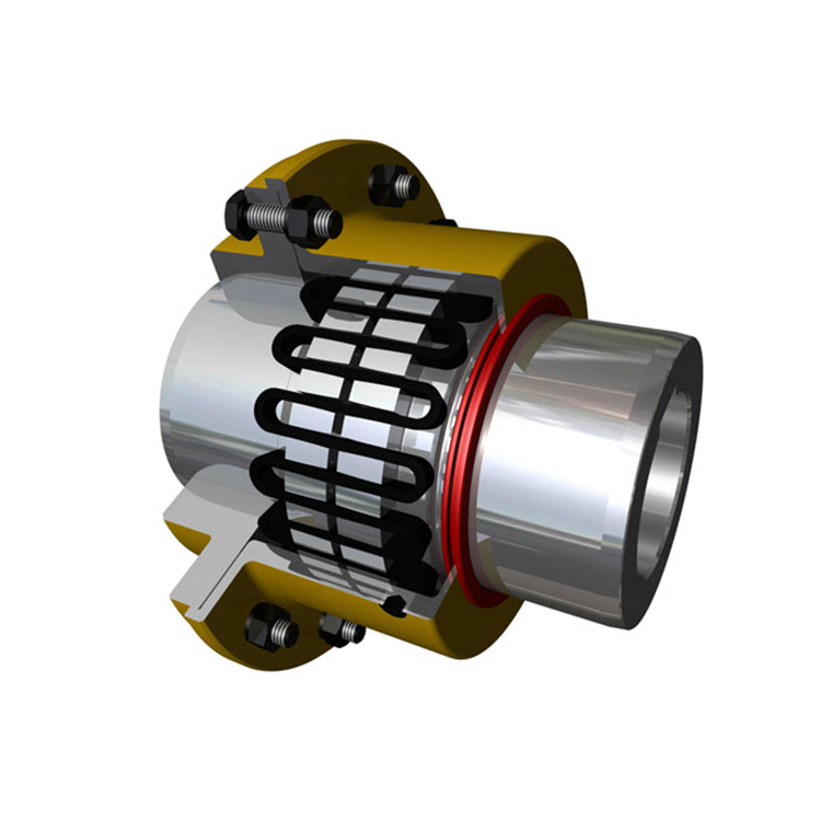
For grid coupling designs, peak torque capacity is typically 200-300% of the continuous rating, depending on the specific model and size. The grid spring's progressive engagement within the hub tooth profile enables this overload capability: as torque increases, more of the grid surface contacts more of the hub tooth surface, distributing the peak load across a progressively larger contact area. This distributed loading is what allows the grid coupling to handle torque spikes that would fracture a rigid component.
The peak torque rating must never be confused with a continuous operating limit. Even though the coupling can survive brief peaks, repeated operation at or near peak torque accelerates fatigue damage and reduces the coupling's effective service life. Each significant peak event — those exceeding 150% of continuous rating — consumes a portion of the coupling's fatigue life budget, even when no visible damage occurs during the event itself.
Service Factors: Matching Coupling to Application Severity
Service factors translate application loading conditions into a sizing multiplier that adjusts the continuous torque rating to a selection torque value. The grid coupling manufacturer publishes standard service factor tables that categorize applications by load type, from uniform loads with no shock to severe shock loads with frequent reversals. Applying the correct service factor ensures the selected coupling has adequate capacity for the real-world conditions it will face.
Uniform load applications — centrifugal pumps, fans, and light-duty conveyors — typically use service factors of 1.0-1.25. The coupling transmits torque that varies only slightly from the nominal value, with no significant peaks or reversals. Moderate shock applications — gearboxes driving reciprocating equipment, larger conveyors, and positive displacement pumps — require factors of 1.5-2.0 to account for the regular torque variations inherent in these drives.
Heavy shock applications — jaw crushers, hammer mills, and reversing drives — demand service factors of 2.0-3.0. The torque peaks in these applications can reach 2-4 times nominal torque during jam events or direction reversals, and the frequency of these events determines whether the coupling's overload margin is adequate. Underspecifying the service factor for a heavy shock application is one of the most common causes of premature grid coupling failure.
Calculating the Correct Coupling Size from Torque Requirements
The proper sizing calculation for a grid coupling follows a systematic process. First, determine the nominal torque of the driven equipment from the motor nameplate horsepower and operating speed using the fundamental power-torque relationship. Then multiply by the applicable service factor to obtain the selection torque. Finally, select the smallest coupling size with a continuous torque rating equal to or exceeding the selection torque.
The nominal torque calculation uses the formula: Torque (Nm) = (Power (kW) × 9,550) / Speed (RPM). For a 150 kW motor operating at 1,780 RPM, the nominal torque is approximately 806 Nm. With a 1.5 service factor for a conveyor application, the selection torque is 1,209 Nm, requiring a coupling with at least this continuous torque rating.
Verification steps follow the initial sizing. Confirm that the selected coupling's maximum bore accommodates the shaft diameter with appropriate fit. Verify that the operating speed is below the coupling's speed rating. Check that the actual installation misalignment falls within the coupling's rated misalignment capacity. Only when all three verifications pass does the selected coupling represent a complete, appropriate match for the application.
Speed Effects on Torque Capacity
The relationship between speed and grid coupling torque capacity deserves specific attention in variable-speed and high-speed applications. Standard torque ratings assume operation at the coupling's reference speed — typically 100-200 RPM for large industrial sizes and 500-1,000 RPM for smaller sizes. At significantly higher or lower speeds, the effective torque capacity may differ from the published rating.
At low speeds, the coupling's torque capacity is essentially unaffected because the centrifugal and dynamic forces that change behavior at high speed are negligible. However, low-speed applications may require checking the minimum speed for adequate lubrication film formation — some couplings need a minimum RPM to maintain adequate lubricant flow to the tooth contact surfaces.
At high speeds above approximately 75% of the coupling's rated maximum, centrifugal forces begin reducing the effective engagement between the grid and hub teeth. This reduction decreases the effective torque capacity, requiring application of manufacturer-provided speed derating factors to the published continuous torque rating. Failing to apply these derating factors when operating at high speeds results in a coupling that is effectively undersized for the application.
Misalignment Interaction with Torque Capacity
Misalignment and torque capacity interact in ways that are not always intuitive. A grid coupling operating at rated torque within rated misalignment limits experiences approximately the same stress levels as one operating at rated torque with perfect alignment. However, operating at rated torque while exceeding rated misalignment capacity concentrates stress in the loaded tooth flanks, dramatically reducing the effective torque capacity and service life.
Angular misalignment generates additional bending stresses in the grid that add to the torsional stress from torque transmission. The combined stress level at maximum misalignment and maximum torque may exceed the material fatigue limit even when each individual factor would be acceptable within its own limit. This interaction is why service factors and misalignment capacity must be evaluated together rather than independently.
Practical alignment targets for grid coupling installations aim for 50-60% of rated misalignment capacity during operation. This margin accommodates the dynamic misalignment changes that occur during thermal cycling and load variations, ensuring the coupling never operates at its misalignment limit while simultaneously transmitting high torque.
Frequently Asked Questions
What is the difference between continuous torque and selection torque?
Continuous torque is the maximum torque the coupling can transmit indefinitely under ideal conditions — rated speed, proper alignment, and adequate lubrication. Selection torque is the continuous torque multiplied by the service factor, representing the torque level the coupling must handle in the actual application. The coupling is selected so that its continuous torque rating equals or exceeds the selection torque.
How do I determine the correct service factor for my application?
Consult the service factor table published by the coupling manufacturer. These tables categorize equipment types by load severity — uniform, moderate shock, or heavy shock — and assign corresponding factors. When the application falls between categories or involves unusual operating conditions, apply engineering judgment to select the conservative factor. It is safer to oversize the coupling slightly than to use a factor that underestimates the application severity.
Can a grid coupling handle repeated motor starting torque?
Yes, provided the starting torque does not consistently exceed the coupling's peak torque rating and the starting frequency does not consume the fatigue life budget too rapidly. Motor starting typically produces torque peaks of 150-200% of nominal torque for 1-3 seconds. A properly sized grid coupling handles thousands of these events during its service life without damage, as each peak falls well below the peak torque capacity.
What happens if the coupling is undersized for the application?
An undersized grid coupling operates continuously above its fatigue limit, accumulating damage faster than the grid can sustain. The grid develops fatigue cracks within weeks or months, leading to grid fracture, loss of torque transmission, and sudden equipment shutdown. The cost of an unplanned shutdown — lost production, emergency repair labor, and potential secondary equipment damage — vastly exceeds the cost of selecting an adequately sized coupling from the beginning.
Conclusion
Understanding grid coupling torque capacity — continuous ratings, peak capacity, service factors, speed derating, and misalignment interactions — enables engineers to select couplings that perform reliably throughout their intended service life. Each parameter addresses a specific aspect of real-world operation, and overlooking any one of them creates risk that the coupling will fail prematurely. A systematic sizing process that applies all relevant torque-related considerations produces selections that consistently deliver the 3-5 year service life that properly maintained grid couplings are designed to achieve.
References
AGMA 9002-B04 — Flexible Couplings: Design Considerations and Selection
ISO 14691:2008 — Flexible Couplings: Design, Selection and Application
API 671 — Special Purpose Couplings for Petroleum, Chemical, and Gas Industry Services
Shigley, J.E. et al. (2020). Shigley's Mechanical Engineering Design, 12th Edition. McGraw-Hill.
Brasel, J.N. (2010). "Failure Analysis of Grid Couplings in Heavy-Duty Applications." Journal of Mechanical Design, 132(8), 081001.