

Specifying a grid coupling from a reliable grid coupling manufacturer is one thing; understanding how that coupling was made is another. The performance gap between two couplings that look identical on paper often traces back to differences in the production line — how the steel was sourced, how the grid spring was formed, how tightly the machining tolerances were held, and how aggressively the coupling supplier enforced inspection at each stage. For procurement teams buying in volume, those differences decide whether a shipment performs for five years or fails inside eighteen months. A purchasing decision based only on price and catalog rating misses the factor that actually predicts field life.
This walk-through covers the actual production steps inside a grid coupling factory and the control points that separate a production-grade coupling from a compromised one. The same principles apply whether the buyer needs a single replacement or a multi-year supply agreement.
Raw Material Control Before the First Cut
Manufacturing discipline starts at the material certification desk, not on the shop floor. Every bar of spring steel destined for a grid element arrives with a mill test report stating chemistry, grain size, and deoxidation practice. A responsible coupling manufacturer quarantines incoming steel until those certificates are matched against the purchase order and a spectroanalysis sample confirms the grade. Skipping this step is how mixed heats enter production and quietly change fatigue behavior in a way that never shows up until the coupling is in service.
Hub blanks follow the same gate. Alloy steel for heavy-duty sizes is verified for hardenability band compliance before it is roughed. The cost of rejecting a non-conforming heat at receiving is trivial next to the field cost of a batch of couplings with inconsistent tooth hardness. Volume buyers should ask whether their grid coupling supplier performs incoming verification or simply trusts the mill certificate without confirmation.
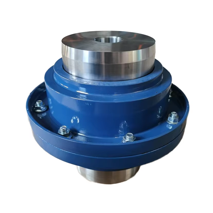
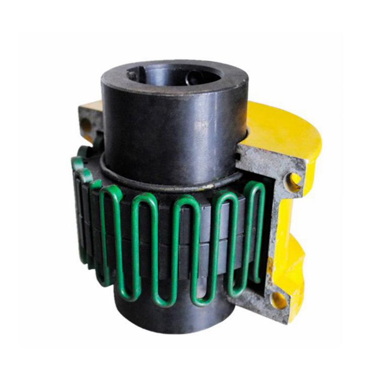
Forming the Grid Spring Element
The grid spring is the component that actually flexes under load, so its forming process receives the most scrutiny in any serious grid coupling manufacturing operation. Cold coiling or specialized forming presses shape the serpentine profile from calibrated spring wire, holding the cross-section within a tolerance band that directly governs fatigue life. A grid that is 8% thin in one segment carries a disproportionate share of the load and becomes the crack-initiation point that ends the coupling early.
Experienced suppliers run first-article validation on every forming tool change. The grid pitch, crown radius, and free-state height are measured against the master drawing before a production run proceeds. Tooling wear is monitored by sampling grid geometry at fixed intervals rather than waiting for a field complaint. This discipline is what lets a coupling factory ship consistent grids across a multi-year contract instead of grid sets that vary coupling to coupling.
Hub Machining and Tooth Profile Accuracy
Hubs are turned, bored, and keyseated on CNC lathes, then the internal tooth profile is generated by broaching or gear-milling followed by finish grinding. Tooth profile accuracy decides how load spreads across the grid contact length. A coupling factory that grinds the tooth flanks below 0.8 micrometer Ra gets more uniform contact and lower peak stress than one shipping mill-only surfaces, because smoother flanks reduce the friction heat generated each time the grid rocks in the teeth.
Bore and keyway dimensions are verified with bore gauges and keyway go/no-go checks at the machine, not just at final inspection. Hubs bored oversize let the interference fit fall short; hubs bored undersize crack on installation. Both failures are prevented by in-process gauging rather than end-of-line sorting, which only catches the defect after the labor is already spent.
Heat Treatment and Surface Hardness
Grid springs are normalized or stress-relieved after forming to remove residual forming stresses, then the hub teeth are induction or through-hardened to the specified surface band. The grid coupling supplier records furnace temperature logs and quench media checks as part of the production record. Surface hardness on the tooth flanks typically sits in a defined HRC window; below it, wear accelerates, above it, impact toughness drops and teeth chip under shock loading that the coupling was expected to absorb.
Tempering is the step amateurs rush. Under-tempering leaves the hub brittle; over-tempering gives up too much hardness. Production control means furnace soak time and temper temperature are logged per batch and tied to the batch number stamped on the hub, so any future field issue can be traced to the exact thermal cycle that produced the part.
In-Process Inspection and Statistical Control
Modern grid coupling manufacturing leans on statistical process control rather than 100% sorting. Critical characteristics — tooth profile, bore, grid cross-section, hardness — are charted across the run. When a trend line drifts toward a tolerance edge, the line is adjusted before parts go out of spec. This is cheaper and more reliable than inspecting defects out after they exist, and it protects the buyer from receiving a shipment where the marginal parts are clustered at the edge of acceptance.
Laser scanning on coordinate measuring equipment captures full tooth geometry in minutes, flagging crown deviations a touch-probe might miss. The data feeds the same control chart the machinists watch, closing the loop between measurement and adjustment so the next part is corrected rather than the last part scrapped.
Assembly, Lubrication, and Final Verification
Assembly pairs matched hubs with the correct grid, fills the housing with the specified semi-fluid grease, and seats the seals. A coupling manufacturer that controls assembly prevents the silent errors — wrong grid size, under-fill, twisted seal — that surface only after commissioning. Final verification checks free rotation, bolt torque, and external markings, then the unit is tagged with a traceable lot number that follows it through warehousing and onto the truck.
End-of-line spin or runout checks catch the rare hub that seated off-center. Combined with the material and machining records, the finished coupling carries a traceable identity from steel heat to shipping carton, which is exactly what a plant reliability engineer wants when a failure investigation starts.
Why Production Control Protects the Buyer
Volume buyers feel production control as consistency: every coupling from a given grid coupling supplier behaves like the last one, so installation crews stop finding surprises and maintenance can plan intervals with confidence. Inconsistent production shows up as scattered failures, mixed service life, and warranty arguments that consume engineering time. The control systems described here are what let a coupling factory promise a number and ship to it, contract after contract, without the variance that turns a low unit price into a high cost of ownership.
Frequently Asked Questions
What should a buyer request from a grid coupling manufacturer?
Ask for material test certificates, heat treatment logs, and dimensional inspection reports tied to the lot number. A supplier that treats these as standard documentation is running real production control; one that treats them as unusual requests likely is not, and the gap will appear in the field.
Does grid forming method affect coupling life?
Yes. Forming that holds grid cross-section within a tight band avoids load concentration on thin segments. Couplings from a controlled forming process show far less scatter in service life than those from loosely held tooling, which is why fleet operators care about the supplier's forming discipline.
Why does tooth surface finish matter so much?
Grinding the tooth flanks reduces friction heat during flexing and spreads load more evenly. Rough mill-only surfaces concentrate contact stress, raise temperature, and shorten both grid and hub life under the same duty, even when the dimensional tolerances are technically met.
How does a coupling factory prove traceability?
By stamping a lot number on the hub and retaining the steel certificate, heat-treat log, and inspection record against that number. Buyers can then trace any field issue back to its production batch and, if needed, to the specific incoming steel heat.
Conclusion
A grid coupling is only as good as the production discipline behind it. Material verification, controlled grid forming, accurate tooth machining, disciplined heat treatment, statistical in-process inspection, and verified assembly are the control points that turn steel and spring wire into a predictable, long-life component. Procurement teams that evaluate a grid coupling manufacturer on these production capabilities — not just on price and catalog ratings — consistently receive couplings that perform to spec across the whole shipment and across years of service, which is the outcome every supply agreement is supposed to deliver.
References
AGMA 9002-B04 — Flexible Couplings: Design Considerations and Selection
ISO 14691:2008 — Flexible Couplings: Design, Selection and Application
Dieter, G.E. & Schmidt, L.C. (2013). Mechanical Metallurgy: Engineering Materials and Processing, 5th Edition. McGraw-Hill.
Kalpakjian, S. & Schmid, S.R. (2021). Manufacturing Engineering and Technology, 8th Edition. Pearson.
API 671 — Special Purpose Couplings for Petroleum, Chemical, and Gas Industry Services