

Conveyor drives are unforgiving on couplings. A belt that snags, a loaded startup, a transfer point that chokes with material — each event lands a shock on the drivetrain that a pump or fan would never see. The T20 grid coupling earns its place in material handling because its grid spring flexes progressively, taking the hit that would otherwise bend a shaft or crack a gearbox. But placing one correctly on a conveyer head shaft takes more than reading a catalog torque number.
This piece works through what a T20 grid coupling actually meets on a conveyer, how to size it so it survives the duty, and how to keep it running across a long, dusty service life in a real plant rather than a test cell.
What a Conveyor Drive Demands From the Coupling
A conveyer head-end drive is dominated by load variability. Empty belt, full belt, and a material surge each produce different torque, and the transition between them is not smooth. The T20 grid coupling sits between the motor and the reducer — or between reducer and head shaft — and absorbs the torque steps as the belt loading changes second to second.
Unlike a fan that draws steady power, a conveyer can sit near zero load for minutes, then spike as a loaded section arrives. That cycling is what ages couplings. The grid spring's nonlinearity — softer under light load, stiffer as torque climbs — suits exactly this profile, cushioning the step changes that rigid connections would transmit straight into the reducer bearings. A plant that runs a dozen conveyers sees this benefit as fewer reducer overhauls across the fleet.
Shock From Jams and Blockages
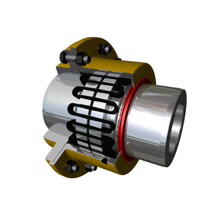
When a conveyer jams, the motor keeps pushing against a stalled load. Torque rises fast, often reaching two to four times the running value before the overload trips. The T20 grid coupling handles this through progressive grid engagement: as torque climbs, more of the grid surface contacts more of the hub tooth surface, spreading the peak over a wider area instead of concentrating it on a few teeth that would otherwise shear.
A supplier sizing a T20 grid coupling for a conveyer should apply a heavy shock service factor, typically in the 2.0 to 2.5 range, because jam events are not rare in bulk handling — they are a normal part of the operating week. Undersizing here is the classic reason a coupling grid cracks within a single season, and the failure usually arrives during the one jam that the overload did not catch in time.
Misalignment Driven by Belt Tension
Conveyer shaft lines drift. Belt tension pulls the head and tail shafts, foundation settling changes elevations over months, and thermal growth during summer operation adds angularity the installer never intended. The T20 grid coupling tolerates this drift within its rated misalignment, keeping the bending stress off the motor and reducer bearings that would otherwise wear early.
In practice, aiming the installed alignment at roughly half the coupling's rated misalignment leaves margin for the drift that accumulates before the next laser-alignment window. Running a conveyer coupling at its misalignment limit from day one means it is already overstressed by the time belt stretch adds another few thousandths of offset, which is when the grid starts showing uneven wear on the loaded flanks.
Sizing the T20 Model for the Head Shaft
Selection starts from the conveyor nameplate power and speed, converts to nominal torque, then multiplies by the shock service factor. A 150 kW head drive at 1,780 RPM gives about 806 Nm nominal; a 2.0 factor pushes the selection torque past 1,600 Nm, which lands the T20 grid coupling in a mid-range model with margin rather than a small unit running at its edge where every jam eats into the fatigue budget.
Then come the checks that get skipped: does the chosen model's maximum bore fit the head shaft with the right interference or clearance fit? Is the operating speed below the model's rating, allowing for any high-speed startup transient? Is the axial displacement capacity enough for the thermal growth expected between cold startup and hot running? A coupling that passes torque but fails the bore or speed check is the wrong coupling for the conveyor, regardless of how clean the torque math looked.
Installation Notes That Prevent Early Failure
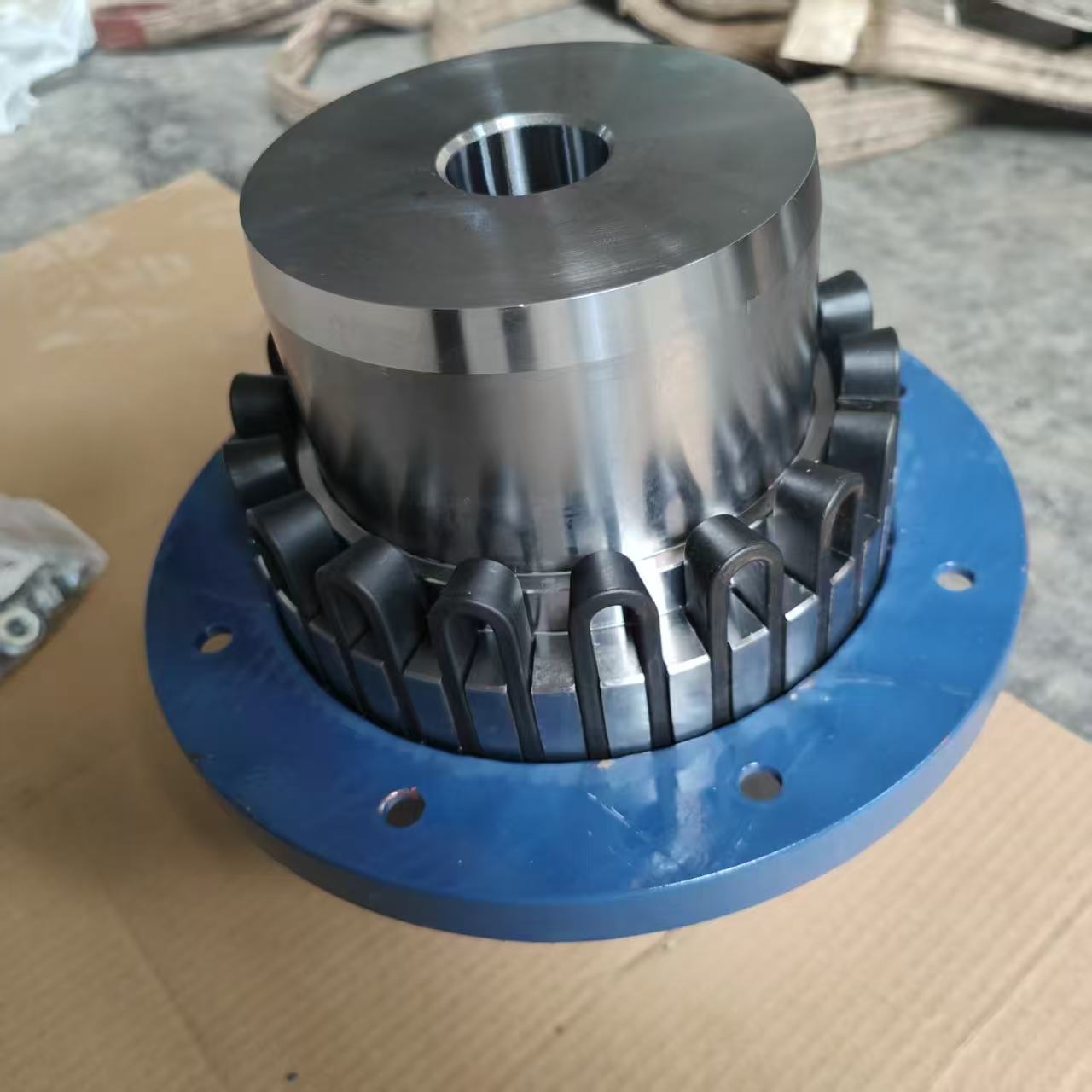
Conveyer couplings are installed in tight head-end housings where access is poor, which tempts crews to rush. The grid must be wound into the hub profile with the proper tool, not levered in with a bar that bends segments past their elastic limit. A T20 grid coupling installed with a damaged grid loses torque capacity before the belt moves a meter, and the damage is invisible until the coupling drops load under the next surge.
Lubrication fill matters on a conveyor because the coupling runs hot from dust and continuous duty. Fill to the level plug, use the specified semi-fluid grease, and resist the urge to overpack — excess grease just pressurizes the cover and forces past the seals onto the belt where it attracts more material. Seals on a T20 grid coupling in a transfer house should be the contact type, not the open labyrinth style meant for clean indoor service where nothing attacks the lip.
Maintenance Cadence in a Dusty Environment
Conveyer houses are among the worst environments for a coupling. Fine material finds every seal gap, mixes with grease, and becomes a lapping compound at the tooth interface. A T20 grid coupling on a conveyer needs shorter inspection intervals than the same coupling on a clean fan — quarterly internal inspection is realistic for heavy-duty transfer points, and monthly external checks catch seal breaches before they contaminate the grease.
At each service, the discharged grease is read like a report: metallic specks mean grid wear, grit means seal breach, darkening means heat. The grid cross-section is measured and compared to the original; past about 15% loss, the grid is changed on a planned outage rather than waiting for the fracture that interrupts the production line during the worst possible shift.
Why the T20 Grid Coupling Fits Material Handling
Material handling rewards a coupling that shrugs off shock and keeps misalignment off the bearings. The T20 grid coupling does both, with a grid element that is cheap to stock and quick to swap. For a plant running dozens of conveyers, that combination — robust duty behavior plus low-cost planned replacement — is what keeps the conveying system available instead of consuming maintenance hours on reactive repairs that the next jam undoes anyway.
Frequently Asked Questions
What service factor suits a T20 grid coupling on a conveyor?
For bulk material handling with jam potential, use a heavy shock factor in the 2.0 to 2.5 band. Light-duty conveyers with smooth, uniform loads can drop toward 1.5, but most plant conveyers see enough surcharge and blockage events to justify the higher figure at selection time.
Can one T20 model serve every conveyor in a plant?
Rarely. Head-end drives, tail-assist drives, and stacker-reclaimer swings have very different torque and speed, so each gets its own model size. Standardizing on one grid cross-section across several T20 sizes helps spare inventory without forcing one coupling to cover incompatible duties.
How often should conveyor coupling grease be changed?
In a dusty transfer house, every three to four months is realistic. Clean indoor conveyers can stretch to six. The deciding factor is what the drained grease shows, not the calendar — if it comes out gritty, the interval was already too long.
Why do conveyor couplings fail sooner than fan couplings?
Dust ingress, shock from jams, and continuous duty in a hot enclosure all accelerate wear. A T20 grid coupling on a conveyor sees a harsher combination of stressors than the same coupling on a clean, steady fan, so shorter life there is expected unless maintenance intervals are tightened to match the environment.
Conclusion
The T20 grid coupling belongs on conveyer systems because it absorbs the shock and misalignment that define material handling duty. Sizing it correctly means applying a realistic shock factor, then verifying bore, speed, and axial capacity against the head-shaft conditions. Kept on a shortened maintenance cadence suited to a dusty enclosure, the coupling delivers the planned grid swaps and bearing protection that keep a conveying system running instead of surprising the maintenance crew with an unplanned stoppage during peak throughput.
References
AGMA 9002-B04 — Flexible Couplings: Design Considerations and Selection
ISO 14691:2008 — Flexible Couplings: Design, Selection and Application
Mancuso, J.R. (1999). Couplings and Joints: Design, Selection, and Application, 2nd Edition. Marcel Dekker.
Brasel, J.N. (2010). "Failure Analysis of Grid Couplings in Heavy-Duty Applications." Journal of Mechanical Design, 132(8), 081001.
API 671 — Special Purpose Couplings for Petroleum, Chemical, and Gas Industry Services